The components of a cooling load are:
- Sensible heat gain: This is the direct addition of heat to the space to be conditioned. It may occur due to any one or all of the following sources of heat transfer:
- The heat flowing into the building by conduction through exterior walls, floors, ceilings, doors and windows due to the temperature difference on their two sides.
- The heat received from solar radiation. It consists of the following:
- The heat transmitted directly through glass of windows, ventilators, and doors.
- The heat absorbed by walls and roofs exposed to solar radiation and later on transferred to the space to be conditioned by conduction.
- The heat conducted from adjoining un-conditioned rooms.
- The heat generated by fans, lights, machinery, cooking operations, industrial processes, etc.
- Occupancy load.
- Air infiltration load through doors, windows, and their frequent opening.
- Heat gain from walls of ducts, etc.
- Latent heat gain: The latent heat load occurs due to the presence of water vapour in the air of conditioned space. This load occurs due to the following sources:
- Moisture in the air entering by infiltration
- Condensation of moisture from occupants, food cooking process.
- Moisture entering directly into the conditioned space through permeable walls, partitions, etc.
1 Heat Transfer Through Walls and Roofs
The heat transferred through a plane wall by conduction is given by Fourier law. For a single wall shown in Fig. 20.28(a), we have
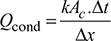
where k = thermal conductivity of wall, W/(m. °C)
Ac = area of wall cross-section, m2
Δt = temperature difference on two sides of wall, °C
Δx = wall thickness, m
The heat transfer by convection from a plane wall is given by Newton’s law
Qconv = hAs Δt
where h = heat transfer coefficient, W/(m2 °C)
As = surface area of wall, m2
Δt = temperature difference between wall and surroundings, °C
Heat gained through a wall by the combined effect of conduction and convention becomes,
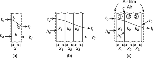
Figure 20.28 Heat transfer by conduction through a plane wall: (a) Single wall, (b) Composite wall, (c) Composite wall with air space

where subscripts o, i refer to outside and inside wall conditions respectively
and U = overall coefficient of heat transfer of wall
 for a single wall (Fig. 20.28a)
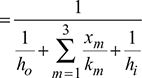 for a composite wall (Fig. 20.28b)
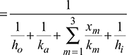 for a composite wall with air gap(Fig. 20.28c)
where ka = thermal conductance of air space
2 Heat Gain from Solar Radiation
The heat from solar radiation is received by building surfaces by direct radiation and diffuse radiation. The direct radiation is the impingement of the Sun’s rays upon the surface. The diffuse radiation is received from moisture and dust particles in atmosphere which absorbs part of the energy of the Sun’s rays. The diffuse radiation is received by surfaces which do not face the sun.
The heat gain through outside walls and roofs is given by,

where Δte = equivalent temperature differential.
3 Sol Air Temperature
It is a hypothetical temperature used to calculate the heat received by the outside surface of a building wall by the combined effect of convection and radiation.
Total heat received by the outside surface of the wall per unit area.
qos = qconv + qrad = ho (to − tos) + I α
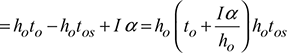

where ![]() = sol air temperature.
= sol air temperature.
t o = temperature of outside air
tos = temperature of outside surface of wall
ho = outside film coefficient
I = total radiation intensity
α = absorptivity of the surface
4 Solar Heat Gain Through Glass Areas

5 Heat Gain Due to Infiltration
There are two methods of estimating the infiltrated air
(i) Crack length method, and (ii) Air change method.
The crack length method is usually used where greater accuracy is required. In most cases the air change method is used for calculating the quantity of infiltrated air. According to this method, the quantity of infiltrated air through windows and walls is,

where L, W, H = length, width and height of room respectively, m
Ac = air changes per hour
Factor ![]() is used because infiltration takes place on the windward side of building only.
is used because infiltration takes place on the windward side of building only.
6 Heat Gain from Products
This heat gain is very important in case of cold storages.
- Chilling load above freezing,
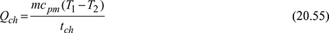 where m = mass of productcpm = mean specific heat of productT1, T2 = initial and final temperature of product respectivelytch = chilling time.
  where hfg = latent heat of freezingtf = freezing time
- Cooling load below freezing,
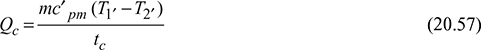 where c’ pm = mean specific heat of freezing productT1′ T2′ = actual storage and freezing temperatures of producttc = cooling time
7 Heat Gain from Lights
Heat gain from lights, Qt = total wattage of lights × use factor × allowance factor

= 0.5 for industrial workshops
Allowance factor = 1.25 for flourescent tubes.
8 Heat Gain from Power Equipments

where ηem = efficiency of electric motor.
9 Heat Gain Through Ducts

where U = overall heat transfer coefficient
AD = surface area of duct
ta, ts = temperatures of ambient and supply airs respectively
10 Empirical Methods to Evaluate Heat Transfer Through Walls and Roofs
There are two approaches to calculate empirically heat transfer through walls and roofs.
They are:
- The decrement factor and time lag method.
- The equivalent temperature differential method.
Both the methods use analytical-experimental results for their formulations. The equivalent temperature differential method is more commonly used by the air-conditioning engineers as it is also applicable to sunlit walls and roofs.
- Using Decrement Factor and Time Lag: If the thermal capacity of the wall is ignored, then the instantaneous rate of heat transfer through the wall at any time τ is given byQτ = UA(te − ti)where te = sol-air temperature.and on an average basis, the mean heat flow is given byQm = UA(tem – ti)where tem = mean sol-air temperature.For the sake of simplicity, the dot above Q has been dropped to indicate the rate.But most building materials have a finite thermal capacity which is expressed asmc = ρcV = ρc(AΔx)where m = Mass of wall, V = volume of wallρ, c = Density and specific heat of wall materialA = Cross-sectional area of wallΔx = Wall thickness.It has been seen that there is a two-fold effect of thermal capacity on heat transfer
- There is a time lag between the heat transfer at the outside surface qo and the heat transfer at the inside surface qi, defined by ϕ.
- There is a decrement in the heat transfer due to the absorption of heat by the wall and subsequent transfer of a part of this heat back to the outside air when its temperature is lower, defined by λ.
- Equivalent temperature differential (ETD) method: The actual heat transfer can be written in terms of an equivalent temperature differential ΔtE defined by the equation.Q = UAΔtEwhere ΔtE = (tem − ti) + λ(te τ − ϕ − tem)ΔtE depends on the following:
- l and f, which in turn depend on the thermo-physical properties of construction.
- Outside air temperature t0 and solar radiation intensity I.
- Room temperature ti.
Leave a Reply