The schematic diagram of a simple vapour compression refrigeration system is shown in Fig. 19.1. It consists of the following parts:
- Compressor.
- Condenser
- Throttle valve
- Evaporators.
- Compressor: The low pressure and temperature vapour refrigerant from the evaporator is drawn into the compressor through the suction valve. It is compressed to a high pressure and temperatures in the compressor. The high pressure and temperature vapours are discharged into the condenser through the delivery valve.
- Condenser: The condenser or cooler consists of coils of pipes in which the high pressure and temperature vapour refrigerant is cooled and condensed. The refrigerant, while passing through the condenser coils gives up its latent heat to the condensing medium. The condensing medium is normally air or water.
- Throttle Valve: Its function is to allow the liquid refrigerant under high pressure and temperature to pass at a controlled rate after reducing its pressure and temperature. Some of the liquid refrigerant evaporates. The enthalpy of the refrigerant remains unaltered in passing through the throttle valve.
- Evaporator: It consists of coils of pipe in which the liquid-vapour refrigerant at low pressure and temperature is evaporated and converted into vapour refrigerant at low pressure and temperature. During evaporation, the liquid-vapour refrigerant absorbs its latent heat of vaporisation from the medium (air, water or brine), which is to be cooled.
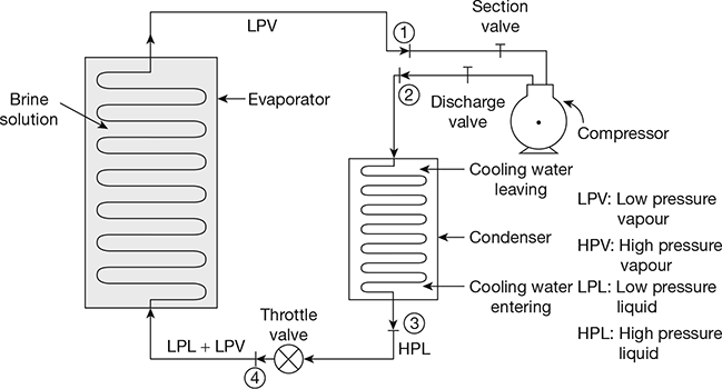
Figure 19.1 Schematic diagram of simple vapour compression refrigeration system
Leave a Reply