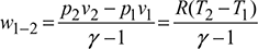
A reversed Carnot cycle, using air as working medium is shown in Fig. 18.5 on p-v and T-s diagrams. The reversed Carnot cycle is represented by four processes as described below:
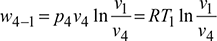
- Process 1-2: Isentropic compressionDuring this process, the pressure of air increases from p1 to p2, specific volume decreases from v1 to v2 and temperature increases from T1 to T2. No heat is absorbed or rejected by air during this process.
- Process 2-3: Isothermal compressionDuring this process, the pressure of air increases from p2 to p3 and specific volume decreases from v2 to v3. Temperature remains constant at T2 = T3.Heat rejected by air per kg of air, q2-3 = area 2-3-3′-2′= T3 (s2 – s3) = T2 (s2 – s3)
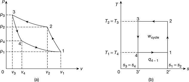 Figure 18.5 Reversed Carnot Cycle: (a) p-v diagram, (b) T-s diagram
 - Process 3-4: Isentropic expansionDuring this process, the pressure of air decreases from p3 to p4, specific volume increases from v3 to v4 and temperature decreases from T3 to T4. No heat is absorbed or rejected by air.
- Process 4-1: Isothermal expansionDuring this process, the pressure of air decreases from p4 to p1 and specific volume increases from v4 to v3. Temperature remains constant at T4 = T1.
Heat absorbed by air (or heat extracted from cold body) per kg of air.
q4−1 = are 4-1-2′-3′
=T4 (s1 − s4)=T4 (s2 − s3)=T1 (s2 − s3)
Work done during the cycle per kg of air, wcycle = q2−3 − q4−1 = are 1-2-3-4
= T2 (s2 − s3) − T1 (s2 − s3)
= (T2 − T1) (s2 − s3)
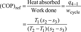
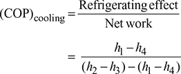
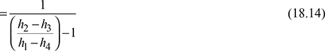
Coefficient of performance of refrigeration system,
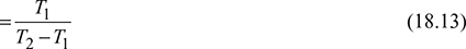
1 Temperature Limitations for Reversed Carnot Cycle
For a reversed Carnot cycle.
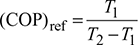
where T1 = lower temperature, and
T2 = higher temperature.
The COP of the reversed Carnot cycle may be improved by the following methods:
- Decreasing the higher temperature T2 of hot body.
- Increasing the lower temperature T1 of cold body.
The temperature T1 and T2 cannot be varied at will, due to certain functional limitations. The lowest possible refrigeration temperature is T1 = 0 (absolute zero) at which (COP)ref = 0. The highest possible refrigeration temperature is T1 = T2 i.e. when the refrigeration temperature is equal to the temperature of the surroundings at which,(COP)ref = ∞. Thus reversed Carnot COP varies between 0 and ∞.
To obtain maximum possible COP in any application,
- the cold body temperature T1 should be as high as possible, and
- the hot body temperature T2 should be as low as possible.
The lower the refrigeration temperature required and higher the temperature of heat rejection to the surroundings, the larger is the power consumption of the refrigerating machine. Also, the lower is the refrigeration temperature required, the lower is the refrigerating capacity obtained.
The temperature T2 in winter is less than T2 in summer. Therefore, (COP)ref in winter will be higher than (COP)ref in summer. In other words, the Carnot refrigerator works more efficiently in winter than in summer. Similarly, if the lower temperature fixed by the refrigeration application is high, the (COP)ref will be high. Thus a Carnot refrigerator used for making ice at 0°C (273 K) will have less (COP)ref than a Carnot refrigerator used for air-conditioning plant in summer at 20°C when the ambient air temperature is 40°C.
2 Vapour as a Refrigerant in Reversed Carnot Cycle
The reversed Carnot cycle can be made almost practical by operating in the liquid-vapour region of a pure substance as shown in Fig. 18.6 on T-s diagram.
- Process 1-2: Isentropic compressionThe vapours during compression are wet and becomes dry saturated at the end of the process. Such a process is called wet compression. The temperature rises from T1 to T2.Compression work per kg of refrigerant, w1−2 = h2 − h1
- Process 2-3: CondensationDuring this process the temperature remains constant at T2. Heat is rejected from h2 to h3 and refrigerant gets converted to liquid at the end of process.q2−3 = h2 − h3 = (hfg)t2
- Process 3-4: Isentropic expansionDuring this process the flashing of the liquid refrigerant takes place with consequent temperature drop from T2 to T1. The refrigerant becomes wet at the end of expansion.Work of expander, w3−4 = h3 − h4
- Process 4-1: EvaporationDuring this process the wet refrigerant evaporates, heat is absorbed from the medium, and refrigeration effect is produced.
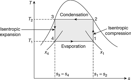 Figure 18.6 Reversed Carnot cycle with vapour as a refrigerant
Network, wnet = w1−2 −w3−4 = (h2 − h1) −(h3 − h4)
= (h2 − h3) −(h1 − h4)= q2−3 − q4−1
Example 18.6
A Carnot refrigerator has working temperatures of −30°C and 35°C. It operates with R-12 refrigerant as a working substance. Calculate the work of isentropic compression, isentropic expansion, refrigeration effect, and COP of the cycle per kg of refrigerant.
If the actual COP is 80 percent of the maximum, calculate the power consumption and heat rejected to the surroundings per ton of refrigeration.
Solution
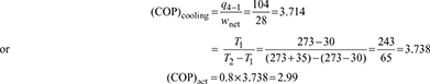
Given: t1= −30°C, t2 = 35°C, Refrigerant = R-12, (COP)actual = 0.8(COP)max From the table of properties of R-12, we have (Refer to Fig. 18.6)
s1 = s2 = 0.6839 kJ/(kg.K), s3 = s4 = 0.2559 kJ/(kg.K), h2 = 201.5 kJ/kg.
h3 = 69.5 kJ/kg, sf1 = sf4 = 0.0371kJ/(kg.K), sg1 = sg4 =0.7171 kJ/(kg.K)
hf1 = hf4 = 8.9 kJ/kg, hg1 = hg4 = 174.2 kJ/kg
Now s1 = sf1 + x1 (sg1 − sf1) = 0.0371+ x1(0.7171− 0.371)
= 0.0371 + 0.68 x1 = 0.6839
x1 = 0.951
h1 = hf1 + x1 (hg1 − hf1) = 8.9+ 0.951(174.2 − 8.9) = 166.1 kJ/kg
s4 = sf4 + x4 (sg4 − sf4) = 0.0371+ x4 (0.7171− 0.0371) = 0.2559
x4 = 0.3218
h4 = hf4 + x4 (hg4 − hf4) = 8.9+ 0.3218 (174.2 −8.9) = 62.1 kJ/kg
Work of compression, w1−2 = h2 − h1 = 201.5−166.1= 35.4 kJ/kg
Work of expression, w3−4 = h3 − h4 = 69.5−62.1= 7.4 kg
Refrigerating effect, q4−1 = h1 − h4 =166.1−62.1=104 kJ/kg
Heat rejected, q2−3 = h2 − h3 = 201.5−69.5=132 kJ/kg
Network, wnet = w1−2 − w3−4 = 35.4 − 7.4 = 28 kJ/kg
Power consumption per ton of refrigeration ![]()
Heat rejected per ton of refrigeration to the surroundings = 3.5167 + 1.1761 = 4.6928 kW
18.10.3 Gas as a Refrigerant in Reversed Carnot Cycle
Figure 18.7 shows the p-v and T-s diagrams for the reversed Carnot cycle with a gas as a refrigerant.
- Process 1-2: Isentropic compressionDuring this process, the pressure increases from p1 to p2 and volume decreases from v1 to v2. Heat transfer is zero so that q1−2 = 0. Temperature of gas increases from T1 to T2. Work done per kg of gas,
- Process 2-3: Isothermal CompressionDuring this process, the pressure increases from p2 to p3 and volume decreases from v2 to v3. The temperature remains constant at T2.
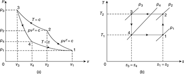 Figure 18.7 Reversed Carnot cycle with gas as a refrigerant: (a) p-v diagram, (b) T-s diagrameWork done per kg of gas,
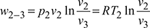 Heat rejected, q2−3 = w2−3 for a perfect gas
 - Process 3-4: Isentropic expansionPressure decreases from p3 to p4, volume increases from v3 to v4 and temperature decreases from T2 = T3 to T4 = T1

- Process 4-1: Isothermal expansionPressure decreases from p4 to p1, volume increases from v4 to v1, and temperature remains constant at T1.Work done,
 Refrigerating effect, q4−1 = w4−1 for a perfect gasNet work of the cycle, wnet = w2−3 −w4−1
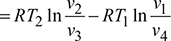 Refrigerating effect,
 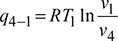 For the isentropic processes 1-2 and 3-4, we have
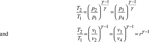 where r = compression ratio for the isentropic processes.
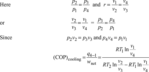
 Thus, COP is a function of compression ratio only.
4 Limitations of Reversed Carnot Cycle
The limitations of reversed Carnot cycle are:
- The isentropic compression and expansion processes require high speed while the isothermal condensation and evaporation processes require an extremely low speed. This variation in speed of air of a cycle is not practicable.
- It is difficult to design an expander to handle a mixture of largely liquid and partly vapour.
- Because of the internal irreversibilities in the compressor and the expander, the actual COP of the reversed Carnot cycle is very low.
- With gas as refrigerant, it is not possible to devise, in practice, isothermal processes of heat absorption and rejection.
- The stroke volume of gas cycle cylinder is very large resulting in poor actual COP.
Leave a Reply