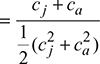
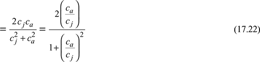
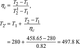
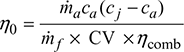
Neglecting the friction and other losses, we have


Example 17.1
A turbo-jet unit consists of single stage compressor, single stage turbine, and nozzle. The pressure and temperature at the inlet of compressor are 0.8 bar and 280 K, respectively. The pressure at the outlet of compressor is 4.5 bar. The following data is available:
Isentropic efficiency of compressor = 0.82
Maximum cycle temperature = 560°C
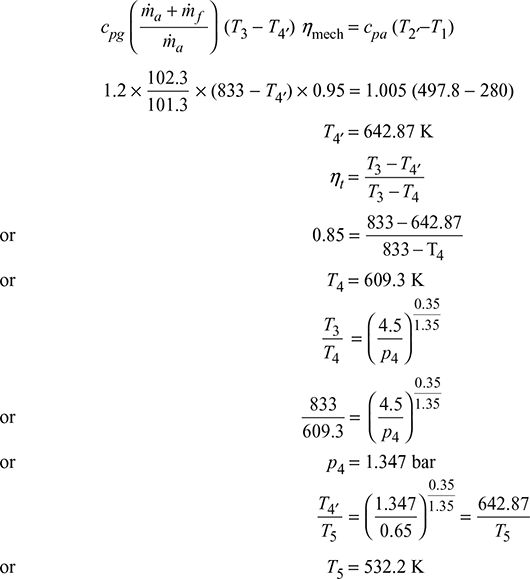
Isentropic efficiency of turbine = 0.85
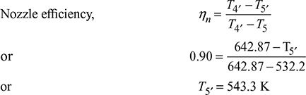
Isentropic efficiency of nozzle = 0.90
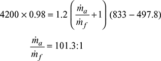
Combustion efficiency = 0.98
Mechanical efficiency = 0.95
cpa = 1.005 kJ/kg.K, γa = 1.4, cpg = 1.2 kJ/kg.K, γg = 1.35
C.V. of fuel used = 42,000 kJ/kg
Static back pressure on the nozzle = 0.65 bar
Speed of aircraft = 720 km/h
Mass rate of flow of air = 20 kg/s
Calculate (a) I.P. required to drive the compressor, (b) A.F. ratio, (c) thrust developed, and (d) the propulsion efficiency.
Solution
The T-s diagram is shown in Fig. 17.8.
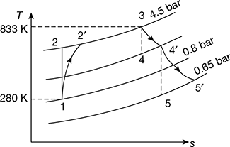
Figure 17.8 T-s diagram for turbo-jet
T3 = 560 + 273 = 833 K
Heat supplied by the fuel = Heat carried by gases from combustion chamber
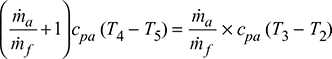
mf × C.V. × ηcomb = cpg (ṁa + ṁf) (T3 − T2′)
No work developed by turbine = work required to run the compressor
I.P. required to run the compressor = ṁa × cpa (T2′ − T1)
= 20 × 1.005 (497.8 − 280) = 4377.78 kW
Heat drop in nozzle, ∆h = cpg (T4′ – T5′)
= 1.2 (642.87 – 543.3)
= 119.484 kJ/kg of air
Velocity of gases learning the nozzle relative to aircraft,

Velocity of aircraft, ![]()
Mass of gases passing through the nozzle, ![]()
Thrust produced = ṁg (cj − ca) = 20.197 (488.84 – 200) = 5833.7 N
Propulsive efficienc ![]()
Example 17.2
In a jet propulsion system, air enters the compressor at 1 bar, 10°C. The pressure leaving the compressor is 4 bar and the maximum temperature is 85°C. The air expands in the turbine to such a pressure that the turbine work is just equal to the compressor work. On leaving the turbine, the air expands in a nozzle to 0.8 bar. Calculate the velocity of air leaving the nozzle. Take cp = 1.005kJ/kg.K and γ = 1.4 for both compression and expansion processes.
Solution
The T-s diagram is shown in Fig. 17.9.
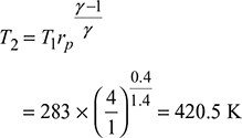
Compressor work, wc = cp (T2 − T1)
= 1.005 (420.5 − 283) = 138.2 kJ/kg of air
T3 = 273 + 850 = 1123 K
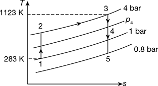
Figure 17.9 T–s diagram for jet propulsion
Now wt = wc = cp (T3 − T4)
or 1.005(1123 − T4) = 138.2
or T4 = 985.46 K
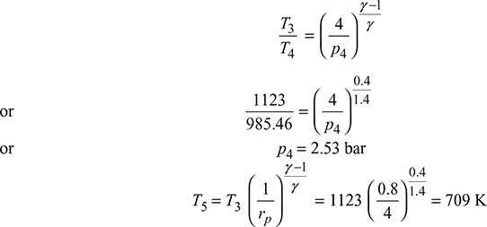
Assuming c4 ≃ 0, ∆h = cp (T4 − T5) = 1.005 (985.46 − 709) = 277.8 kJ/kg

Example 17.3
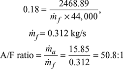
A turbojet engine inducts 40 kg/s of air and propels an aircraft with a uniform flight speed of 900 km/h. The isentropic enthalpy change for nozzle is 190 kJ/kg and its velocity coefficient is 0.96. The fuel-air ratio is 0.015. The combustion efficiency is 0.95 and the lower heating value of the fuel is 44,000 kJ/kg. Calculate the thermal efficiency of the engine, the fuel flow rate and TSFC, the propulsive power, the thrust power, the propulsive efficiency, and the overall efficiency.
Solution
Jet velocity, ![]()
Aircraft velocity, ![]()
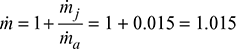
ṁf = 0.015 ma = 0.015 × 40
= 0.6 kg/s or 2160 kg/h
Thrust, F = (ṁa + ṁf) cj − ṁa ca
= (40 + 0.6) × 585.6 − 40 × 250
= 13775 N or 13.775 kN
Thrust specific fuel consumption, TSFC ![]()
Propulsion power, P.P. ![]()
= 5711×103 W = 5711 kW
Thrust power, T.P. = [(ṁa + ṁf)cj − ṁaca] × ca
= (40.6 × 585.6 – 40 × 250) 250
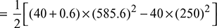
= 3443.86 ×103 W = 3443.86 kW
Propulsive efficiency = ![]()
Overall efficiency = ![]()
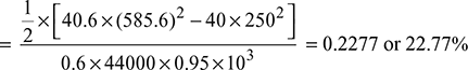
Thermal efficiency, 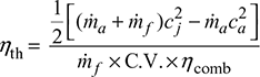
Example 17.4
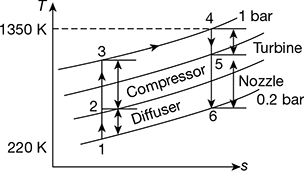
A turbo-jet unit is flying at a speed of 268 m/s at an altitude where the ambient conditions are 0.2 bar and 220 K. The air enters an ideal diffuser and leaves the compressor at 1350 K and 1 bar. The fuel supplied has a heating value of 43,000 kJ/kg. Assume all compression and expansion processes to be isentropic. Determine (a) the air-fuel ratio, (b) the specific thrust, and (c) the propulsive efficiency. Take Cpa = 1.005 KJ/kg.K and γa = 1.4 for compression and Cpg = 1.102 KJ/kg, γg = 1.33 for expansion.
Solution
The T-s diagram is shown in Fig. 17.10.
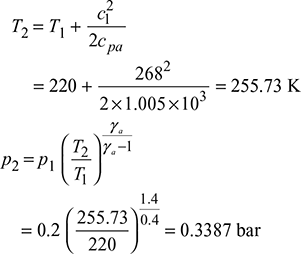
Diffuser:
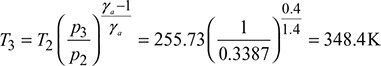
Compressor:
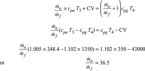
Combustion chamber:
T4 = 1350 K
h3 + q3−4 = h4
ṁa cpa T3 + ṁf × CV = (ṁa + ṁf) cpg T4
Turbine:
wt = wc
(ṁa + ṁf) cpg (T4 − T5) = ṁa × cpa (T3 − T2)
37.5 × 1.102 (1350 − T5) = 36.5 × 1.005 (348.4 − 255.73)
or T5 = 1267.77 K
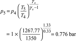
Let p6 = 0.2 bar
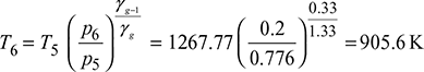
Work output = (ṁa + ṁf) cpg (T5 − T6)
Specific thrust = work output per kg of fuel consumed
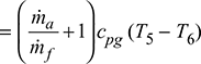
= 37.5 × 1.102 (1267.77 − 905.6)
= 14966.4 kN/kg
Jet velocity, ![]()

Propulsive efficiency, neglecting fuel mass as compared to air mass,
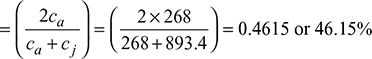
Example 17.5
A turbojet engine consumes air at the rate of 60 kg/s when flying at a speed of 960 km/h. Calculate the following:
- Exit velocity of the jet when the enthalpy drop in the nozzle is 220 kJ/kg and velocity coefficient is 0.95.
- Fuel rate of flow for A/F ratio of 60:1,
- Thrust specific fuel consumption (TSFC),
- Thermal efficiency of the engine assuming combustion efficiency 92% and calorific value of fuel used 43,000 kJ/kg,
- Propulsive power,
- Propulsive efficiency, and
- Overall efficiency
Solution
- Exit velocity of jet,

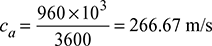
- Fuel rate of flow,
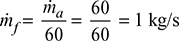
- Thrust produced, F = (ṁa + ṁf) cj − ṁa ca
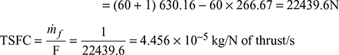
- Thermal efficiency
- Propulsive power
- Propulsive efficiency
- Overall efficiency
Example 17.6
The following data refer to turbo-jet flying at a height of 9000 m:
Speed of turbo-jet = 800 km/h
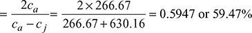
Propulsive efficiency = 54%
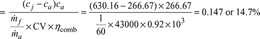
Overall efficiency of plant = 18%
Propulsive force = 6000 N
Calorific value of fuel = 44,000 kJ/kg
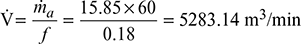
Calculate (a) absolute velocity of jet, (b) volume of air compressed per main, (c) diameter of jet, (d) power output of the unit, and (e) air-fuel ratio.
Solution
- Propulsive efficiency,

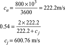 Absolute velocity of jet = cj − ca =600.76 − 222.2 = 378.56 m/s
 - Propulsive force = ṁa (cj − ca)6000 = ṁa × 378.56ṁa = 5.85 kg/sVolume flow rate of air
- Let jet diameter = d
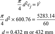
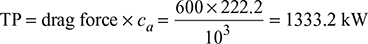
- Thrust power,
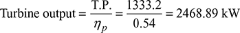
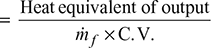
- Overall efficiency
Example 17.7
A high altitude flight jet propeller aircraft is flying with speed corresponding to Mach number of 1.25. The ambient atmospheric pressure and temperature are 0.01MPa and –40°C. The temperature and pressure of gases entering the turbine are 827°C and 0.2 MPa. Isentropic efficiency of compressor and turbine are 0.80 and 0.85, respectively. The ram air efficiency is 0.80. The back pressure on the nozzle may be assumed as the ambient pressure and efficiency of nozzle based on total pressure drop available is 0.90. Neglecting mass increase due to fuel consumed, calculate (a) compressor power per kg per second, (b) air-fuel ratio if the fuel calorific value is 41500 kJ/kg, (c) pressure of gases leaving the turbine, and thrust per kg per second, (d) propulsive efficiency, and (e) thermal and overall efficiency. Assume cpa = 1.005 kJ/kgK, γa = 1.4, cpg = 1.12 kJ/kgK, γa = 1.33.
Solution
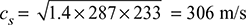
Sonic velocity at ambient conditions,
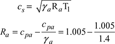
= 0.287kJ/kg.K
T1 = 273 – 40 = 233 K
Speed of aircraft,
ca = 1.25 × 206 = 382.5 m/s
Ramming process 1-2′ (see Fig. 17.11)
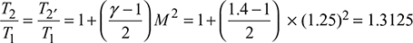
or T2 = T2′ = 233 × .3125 = 305.8 K
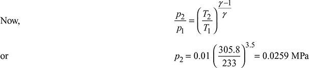
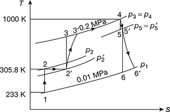
Figure 17.11 T-s diagram for jet propeller
or ![]() = 0.8 (0.0259 − 0.01) + 0.01 = 0.0227 MPa
= 0.8 (0.0259 − 0.01) + 0.01 = 0.0227 MPa
Compressor process 2′–3:
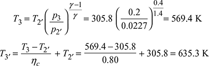
Compressor power, Pc = m cpa (T − T)
= 1 × 1.005 (635.3 − 305.8) = 331.18 kJ/kg/s or kW/kg
Combustion process 3′−4:
T4 = 827 + 273 = 1100 K
Heat supplied, q3′−4 = cpg (T4 − T3′) = 1.12 (1100 – 635.3) = 520.5 kJ/kg
ma cpg (T4 − T3′) = mf × CV
∴ A/F ratio = 79.74:1 = 79.74
Now, wc = wt
or 331.18 = cpg (T4 − T5′) = 1.12 (1100 − T5′)
or T5′ = 804.3 K
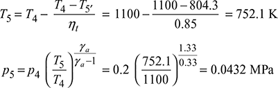
T6′ = T5′ − ηn (T5′ − T6)
= 804.3 – 0.9 (804.3 – 559.4) = 583.9 K
(Δh)nozzle = cpg (T5′ − T6) = 1.12 (804.3 – 583.09) = 246.83 kJ/kg
Thrust c6′ − ca = 702.6 − 382.5 = 320.1 kN/kg/s
Propulsive efficiency, ![]()
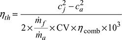
Thermal efficiency, 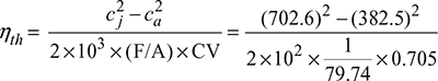
= 0.3337 or 33.37%
Overall efficiency = ηth × ηp = 0.3337 × 0.705
= 0.2352 or 23.52%
Example 17.8
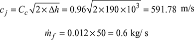
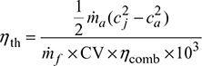
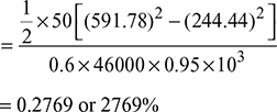
A flying turbojet engine propels at speed of 880 km/h and draws air at the rate of 50 kg/s. Isentropic enthalpy drop in the nozzle is 190 kJ/kg and its velocity coefficient is 0.96. Fuel air ratio used is 0.012. The calorific value of fuel used is 46000 kJ/kg and combustion efficiency is 95%. Find thermal, propulsive, and overall efficiency.
Solution
Given: ![]()
Δh = 190 kJ/kg, Cc = 0.96, F/A = 0.012, CV = 46000 kJ/kg, ηcomb = 0.95,
Example 17.9
The effective jet exit velocity from jet engine is 2700 m/s. The forward flight velocity is 1350 m/s and the air flow rate is 78.6 kg/s. Calculate (a) thrust, (b) thrust power, and (c) propulsive efficiency.
Solution
Given: cj = 2700 m/s, ca = 1350 m/s, ṁa = 78.6 kg/s
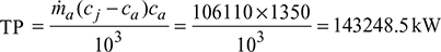
- Thrust, F = ṁa (cj − ca) = 78.6(2700 – 1350) = 106110N
- Thrust power,
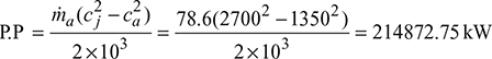
- Propulsive power P.P
 Propulsive efficiency
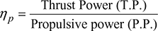
Example 17.10
A simple turbo-jet unit operates with a turbine inlet temperature of 1100 K, a pressure ratio of 4:1 and mass flow of 22.7 kg/s under design conditions. The following component efficiencies may be assumed
Isentropic compressor efficiency = 0.85
Isentropic turbine efficiency = 0.9
Propeller nozzle efficiency = 0.95
Transmission efficiency = 0.99
Combustion chamber pressure loss = 0.21 bar
Calculate the design thrust and specific fuel consumption when the unit is stationary at sea level where the conditions may be taken as 1.013 bar and 288 K.
Solution
Given that T3 = 1100 K, rp = 4, ṁa = 22.7 kg/s, ηc = 0.85, ηt = 0.9, ηn = 0.95, ηmech = 0.99, Δp3 = 0.21 bar, p1 =1.013 bar, T1 = 288 K
Process 1 − 2: Compressor (Fig. 17.12)
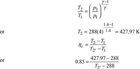
or T2′ = 452.67 K
p3′ = p3 − Δp3 = 4 × 1.013 − 0.21 = 3.842 bar
Neglecting the mass of fuel and cpg = cpa
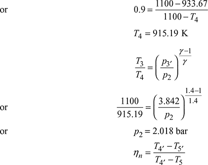
(T3 − T4′)ηmech = T2′ − T1
or (1100 − T4′) × 0.99 = 452.67 − 288
or T4′ = 933.67 K

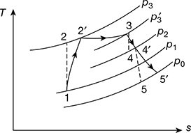
Figure 17.12 T-s diagram for simple turbo-jet
Taking p0 = p1
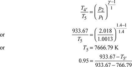
or T5′ = 775.13 K
Enthalpy drops per kg of mass flow rate per second:
(Δh)c = cp (T2′ − T1)
(Δh)t = cp (T3 − T4′)
(Δh)n = cp (T4′ − T5′)
Δh [(Δh)t + (Δh)n] − (Δh)c = cp[T3 − T4′ + T4′ − T5′ − T2′ + T1]
= cp[T3 − T5′ − T2′ − T1] = 1.005[1100 − 775.13 − 452.67 + 288]
= 161 kJ/kg
Velocity of nozzle, ![]()
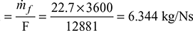
- Design thrust, F = ṁa × cj = 22.7 × 567.45 = 12881 N
- Specific fuel consumption
Example 17.11
In a turbo jet engine, air enters the diffuser at 0.8 bar, 240 K. with a velocity of 1000 km/hr. The pressure, ratio across the compressor is 8. The turbine inlet temperature is 1200 K and the pressure at nozzle exit is 0.8 bar. The turbine work just equals the compressor work input. The diffuser, compressor, turbine and nozzle processes are isentropic and there is no pressure drop for flow through the combustor. Determine the pressure at exit from the diffuser, the compressor, and the turbine, and also the velocity at the nozzle exit. Show the various process on a temperature-entropy diagram. For air, cp 1.001 kJ/kg. K and cp/cv = 1.4.
Solution
Given that p1 = 0.8 bar, T1 = 240 K, c1 = 1000 km/h or 277.78 m/s, ![]() T4 = 1200 K, wt = wc, cpa = 1.001 kJ/kg K, γa = 1.4
T4 = 1200 K, wt = wc, cpa = 1.001 kJ/kg K, γa = 1.4
From Fig. 17.13 we have
p3 = p4, p1 = p6
Assume cpg = cpa and γg = γa = γ
Diffuser:
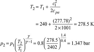
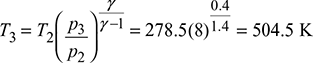
Compressor:
p3 = 8 × 1.34 = 10.778 bar
p4 = p3 = 10.778 bar
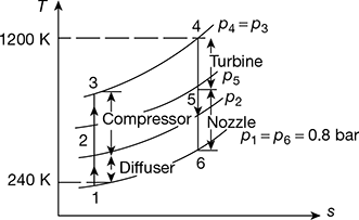
Figure 17.13 Turbo-jet engine T-s diagram
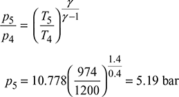
Turbine:
wc = cp (T3 − T2) = 1.001 (504.5 − 278.5) = 226.226 kJ/kg
wt = cp(T4 − T5) = 1.001 (1200 − T5)
Now wt = wc
∴ 1.001 (1200 − T5) = 226.226
or T5 = 974 K
Nozzle: 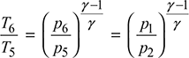
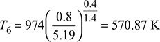
Nozzle jet velocity ![]()

Example 17.12
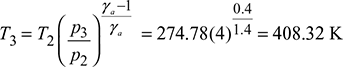
A jet engine is flying at 300 m/s when the pressure and temperature of the atmosphere are 0.8 bar and 230 K, respectively. The compressor pressure ratio is 4 and the maximum cycle temperature is 1000 K. Calculate, specific thrust, power produced, propulsive efficiency, overall thermal efficiency, and the fuel consumption. Assume: isentropic efficiency of components unity; nozzle throat area 0.06 m2; calorific value of fuel 43000 kJ/kg; cp and γ for the combustion and expansion processes 1.15 kJ/kg K and 1.333.
Solution
Given: c1 = 300 m/s, p1 = 0.8 bar, T1 = 230 K, p3/p2 = 4, T4 = 1000 K, ηisen = 1.0, At = 0.06 m2, C.V. = 43000 kJ/kg
cpa = 1.005 kJ/kg. K, γa = 1.4, cpg = 1.15 kJ/kg. K, γg = 1.333
The T−s diagram is shown in Fig. 17.14.
Diffuser:
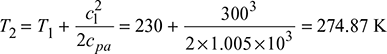
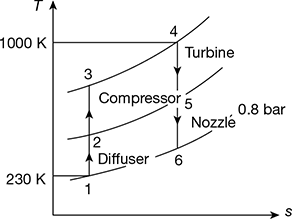
Figure 17.14 T-s diagram for jet engine
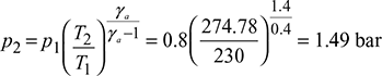
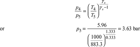
Compressor:
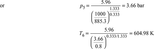
p3 = 4p2 = 4 × 1.49 = 5.96 bar
T4 = 1000 K
Neglecting mass of fuel as compared to that of air,
Work done by turbine = Work done on compressor
cpg (T4 − T5) = cpa (T3 − T2)
1.15 (1000 − T5) = 1.005 (408.32 − 274.78)
or T5 = 883.3 K
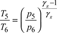
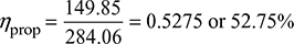
Also p4 = p3
Let p6 = p1 = 0.8 bar
Enthalpy drop in nozzle,
h = cpg (T5 − T6) = 1.15 (883.3 − 605.4) = 319.6 kJ/kg
Velocity of jet, ![]()
Thrust produced, F = ṁ(cj − ca) = 1(799.5 − 800) = 499.5 N/kg of air
Thrust power, ![]()
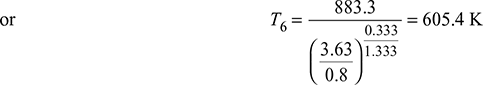
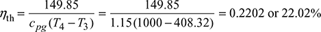
Specific thrust = 149.85 kW/kg of air
Power produced = 149.85 + Turbine output
= 149.85 + 1.15 (1000 − 883.3) = 284.06 kW/kg of air
Propulsive efficiency,
Overall thermal efficiency,
- b. Considering mass of fuel.Let mf = mass of fuel.Then mf × CV = (ma + mf) cpg × T4 − cpa ma T3
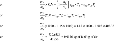 Now Wt = Wc (ma + mf) cpg (T4 − T5) = ma cpa (T3 − T2)or (1 + 0.0176) × 1.15 (1000 − T5) = 1.005 (408.32 − 274.78)or T5 = 885.3 K
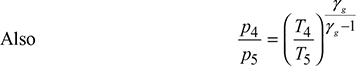
Nozzle:
∆h = cpg (T5 − T6) = 1.15 (885.3 − 604.98) = 322.37 kJ/kg

Specific thrust, 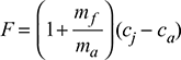
= (1 + 0.0176) (802.95 − 300) = 511.8 N/kg of air
Now 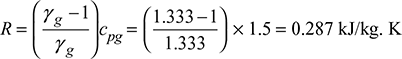
p6v6 = RT6
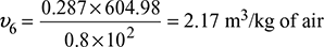
Mass flow rate, 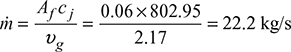
Power produced = F × ca × ṁ/103 = 511.8 × 300 × 22.2/103 = 3408.6 kW
Example 17.13
Air at 25 kPa and 230 K enters a turbojet engine with a velocity of 250 m/s. The pressure ratio across the compressor is 12. The turbine inlet temperature is 1400 K and the pressure at the nozzle exit is 25 kPa. The diffuser, compressor, turbine and nozzle processes are isentropic and there is no pressure drop for flow through the combustor. Draw the line diagram indicating all the components and show the processes on a T–s diagram. Under steady state operating conditions, determine (a) the velocity at the nozzle exit and (b) the pressures and temperatures at each state.
Solution
Diffuser – compressor: The line diagram of turbo-jet and the T–S diagram are shown in Fig. 17.15.
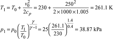
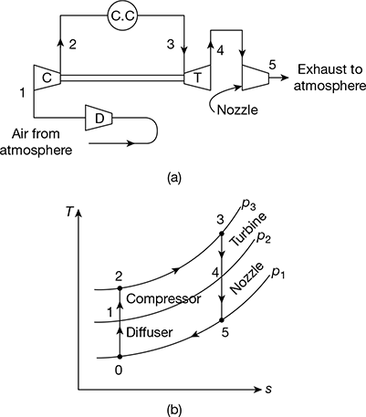
Figure 17.15 Turbo-jet engine: (a) Line diagram of turbo-jet, (b) T-s diagram
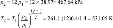
Combustor:
p3 = p2 = 467.64 kPa
T3 = 1400 K
Turbine: Assuming compressor work = turbine work, we have
cp (T2 − T1) = cp (T3 − T4)
or 531.05 − 262.1 = 1400 − T4
or T4 = 1130.05 K
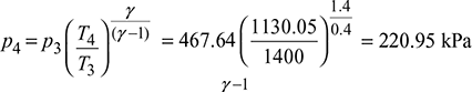
Nozzle: 
c4 ≈ 0 as compared to c5.
c5 = [2 (h4 − h5)]0.5 = [2 × cp (T4 − T5)]0.5
= (2 × 1000)0.5 × [1.005 (1130.5 − 606.3)]0.5
= 1026 m/s
Leave a Reply