Jet propulsion systems may be classified as follows:
- Air stream jet engines: In these engines, the oxygen necessary for combustion is taken from the atmosphere. They are also called air-breathing engines. They may be classified into the following:
- Screw propeller
- Ramjet engine
- Pulse jet engine
- Turbojet engine
- Turboprop engine
- Self-contained rocket engines: In a rocket engine, the full and the oxidiser are contained in the propelling body and thus can function in vacuum as well. They are also called non-air breathing engines. They may be classified into the following:
- Liquid propellant
- Solid propellant
1 Screw Propeller
The line diagram of a screw propeller is shown in Fig. 17.1(a). The schematic arrangement and the corresponding T-s diagram are shown in Fig. 17.1(b) and Fig. 17.1(c), respectively. In this system, full expansion takes place in the turbine, and the total power developed by the turbine is used to drive the compressor and the propeller. The power supplied to the propeller is controlled by controlling the supply of fuel in the combustion chamber. The rate of increase in efficiency of the screw propeller is higher at lower speed but its efficiency falls rapidly at higher speed. It has high power for take-off and higher propulsion efficiency at speed below 600 km/h.
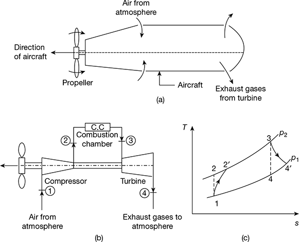
Figure 17.1 Screw propeller: (a) Line diagram, (b) Schematic diagram, (c) T-s diagram
2 Ramjet Engine
The line diagram of a ramjet engine is shown in Fig. 17.2(a) and the corresponding T-s diagram is shown in Fig. 17.2(b). It consists of a supersonic diffuser, subsonic diffuser, combustor, and nozzle. Both supersonic and subsonic diffusers convert the kinetic energy of the entering air into pressure rise. This energy transformation is called the ram effect and the pressure rise is called the ram pressure.
Air from the atmosphere enters the engine at a very high speed and its velocity gets reduced first in the supersonic diffuser, thereby its static pressure increases. The air then enters the subsonic diffuser wherein it is compressed further and its pressure and temperature reaches above the ignition temperature. Later, the air flows into the combustion chamber, the fuel is injected and mixed with the unburnt air. The high pressure and high temperature gases are passed through the nozzle, converting the pressure energy into kinetic energy. The high velocity gases leaving the nozzle provide the required forward thrust to the ramjet.
The major advantages of ramjet engines are as follows: light in weight, no moving parts, and possibility of using a wide variety of fuels. However, its main drawback is that it cannot be started on its own from rest and requires some launching device. Due to its high thrust at high operational speed, it is widely used in high-speed military aircrafts and missiles. Subsonic ramjets are used in target weapons, in conjunction with turbojets or rockets for getting the starting torque. It can be used for pilotless aircraft.
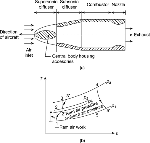
Figure 17.2 Ramjet engine: (a) Line diagram, (b) T-s diagram
3 Pulse Jet Engine
The line diagram of a pulse jet engine is shown in Fig. 17.3. It consists essentially of a diffuser, valve grid, combustion chamber, spark plug, and a tail pipe or discharge nozzle. It is an intermittent combustion engine and operates similar to a reciprocating engine. It develops thrust by a high velocity of jet of exhaust gases without the aid of a compressor or turbine.
The incoming air is compressed by the ram effect in the diffuser and the grid passages which are opened and closed by V-shaped non-return valves. The fuel is then injected into the combustion chamber by fuel injectors. The combustion is then initiated by a spark plug. As a result of combustion, the temperature and pressure of combustion products increase and the non-return valves get closed; consequently, the hot gases flow out. The static pressure in the chamber falls and the high pressure air in the diffuser forces the valves to open and fresh air is admitted for the new cycle.
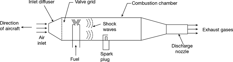
Figure 17.3 Pulse-jet engine
Its main advantages are that it is simple in construction, very inexpensive as compared to turbo-jet engine, and well adaptable to pilotless aircrafts. It is also capable of producing static thrust.
Its major shortcomings are: high intensity of noise, severe vibrations, high rate of fuel consumption, low efficiency, intermittent combustion, limited operational attitude and serious limitations of mechanical valve arrangement.
4 Turbo-jet Engine
The line diagram of the turbojet unit is shown in Fig. 17.4(a). The schematic arrangement and the corresponding T-s diagram are shown in Fig. 17.4(b) and Fig. 17.4(c), respectively. It consists of a diffuser, compressor, combustion chamber, turbine, and exhaust nozzle.
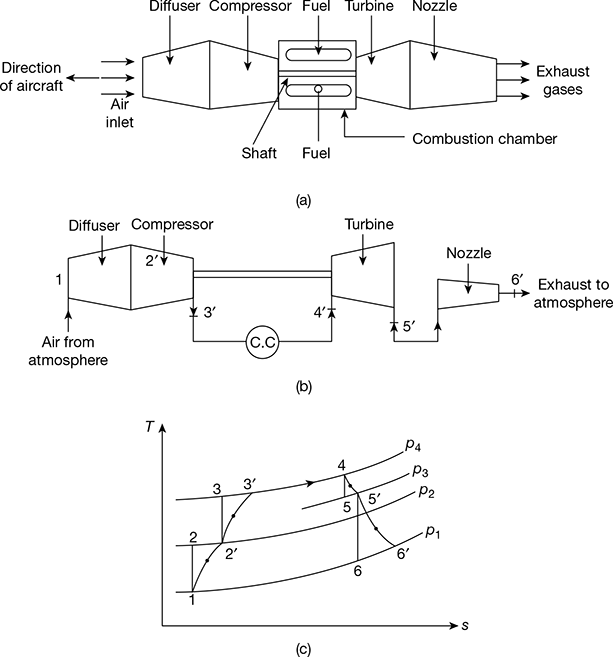
Figure 17.4 Turbo-jet engine: (a) Line diagram, (b) Schematic diagram, (c) T-s diagram
The function of the diffuser is to convert the kinetic energy of the entering air into a static pressure rise, which is achieved by the ram effect. This air enters the axial flow compressor and combustion chamber. The gas turbine produces just sufficient power to drive the compressor by partial expansion in the turbine. The gases coming out from the turbine are expanded in the nozzle and produce a very high velocity jet which gives a forward motion to the aircraft by the jet reaction.
The advantages of a turbo-jet engine are its simpler construction, absence of vibrations, uninterrupted and smooth operation, lesser weight to power ratio, higher rate of climb, and higher propulsion efficiency at higher speed. However, its disadvantages are less efficiency, shorter life, noisier, expansive, larger length of take-off required, and low thrust at take-off.
It is suitable for piloted operation of aircraft travelling above 800 km/h.
5 Turbo-Prop Engine
The line diagram of a turbo-prop engine is shown in Fig. 17.5(a) and the corresponding T-s diagram in Fig. 17.5(b). The engine consists of propeller, reduction gear, diffuser, compressor, combustion chamber, turbine, and exhaust nozzle. In this system, the gases are partly expanded in the turbine and partly in the nozzle. The total power produced by the turbine is used to run the compressor and the propeller. The propeller provides most of the propulsive thrust and the thrust produced due to jet action is quite small.
The turbo-prop combines the merits of a turbo-jet and a propeller. It is suitable for piloted operation of aircraft.
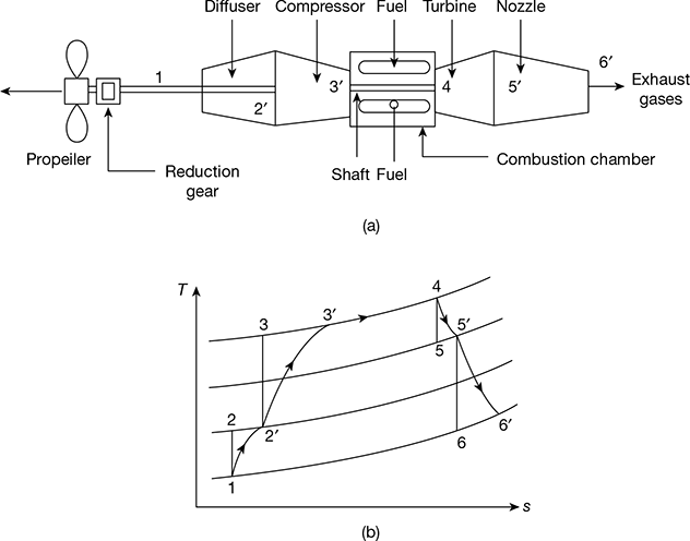
Figure 17.5 Turboprop engine: (a) Line diagram, (b) T-s diagram
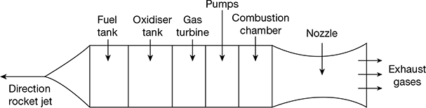
Figure 17.6 Line diagram of a rocket jet
6 Rocket Propulsion
In a rocket engine, the fuel and the oxidiser are stored in the propelling body. The rocket can function in a vacuum and is the only device capable of space flight.
Rockets may be of the single-stage or multi-stage type, consisting of one or more rocket motors. They may be solid propellant or liquid propellant rockets.
Figure 17.6 shows the line diagram of a liquid propellant rocket engine using liquid oxygen and refined petrol. It consists of a fuel tank, oxidiser tank, gas turbine, pumps, combustion chamber, and nozzle. Pumps are used to supply propellants to the nozzle at high pressure to obtain higher thrust. These pumps are operated by a gas turbine where the high pressure and high temperature gases formed by the fuel and oxidiser are delivered to the gas turbine.
The properties for an ideal propellant are high calorific value, high density, high stability, ease of handling and storing, non-corrosive, and high boiling point at low pressure.
Rockets find important applications in the field of long range artillery, lethal weapons, signalling and fireworks, jet assisted take-off, satellites, space ships, and research. They are suitable for pilotless operation.
Leave a Reply