Figure 15.5 shows the velocity triangles for one stage of an axial flow compressor. All angles are measured from the axial direction. The blade velocity u is taken to be same at blade entry and exit as the air enters and leaves the blades at almost equal radii. Due to the diffusion process in the moving blades, vr2 < vr1 but va2 > va1. The air leaves the fixed blades with velocity va3 at an angle α3 and is redirected to the next page. It is assumed that va1 = va3.
From the inlet velocity triangle, we have
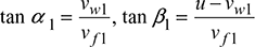
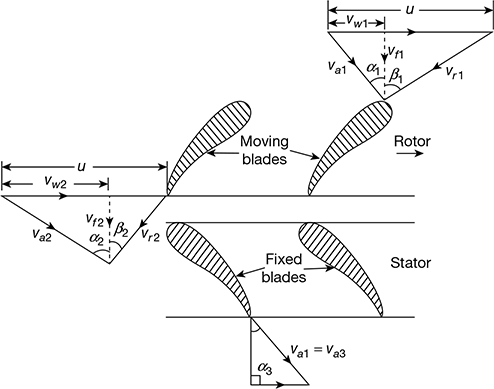
Figure 15.5 Velocity diagrams for axial flow compressor

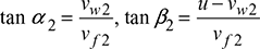
From the outlet velocity triangle, we have

Assuming 1 kg flow of air through the compressor stage, we have
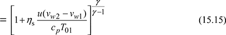
Tangential force per kg of air = vw2 − vw1
Work required by the stage per kg of air,

Now vf1 = vf2 = vf


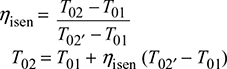
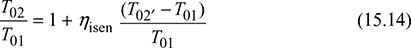
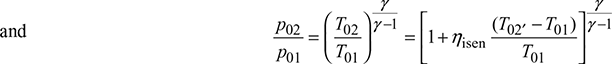
Also, isentropic efficiency of the stage,
Leave a Reply