When an object is placed within a fluid stream, a force is exerted on the object which may be inclined to the flow direction. The component of this force parallel to the direction of flow is called the drag and the normal component is called the lift, as shown in Fig. 15.2.
Consider an aerofoil section as shown in Fig. 15.3, which has an angle of attack α, the chord length C, and the length of the foil perpendicular to the plane of the paper, termed as the span, l. The resultant force F executed by the fluid on the aerofoil has two mutually perpendicular components: the lift FL and the drag FD. Consider a surface element of elementary area dA of aerofoil on which pressure p acts. Let the tangent to dA make an angle θ with the flow direction. The differential lift and drag on this area element are as follows:
dFL = pdA cos θ
dFD = pdA sin θ
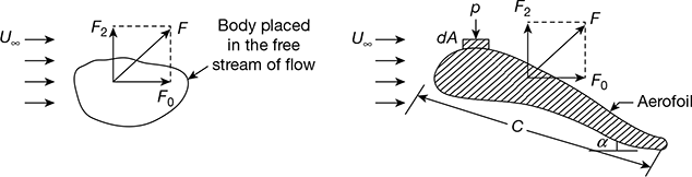
Figure 15.2 Definition sketch of lift and drag
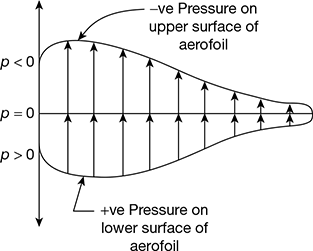
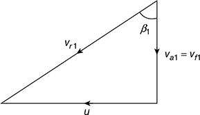
Figure 15.3 Pressure distribution on an aerofoil section
Lift, FL = ∫A pdAcosθ
Drag, FD = ∫A pdAsinθ
where ∫A represents the integration over the entire body surface area A.
We define the following lift and drag coefficients:


where ρ = density of air stream
U∞ = free stream velocity of air
A = projected area of the body perpendicular to the oncoming flow, i.e., the frontal area of the body.
Let
V̇ = free air delivered by the compressor, m3/min
i = number of moving blades per blade ring
p1, T1 = ambient air conditions
Dm = blade ring mean diameter, m
kb = blade factor
h = blade height, m
N = rotor speed, rpm
CL, CD = lift and drag coefficients respectively
A = projected area of blades, m2
Then density of air, ![]()
V̇ = vaA
A = kbπDmh
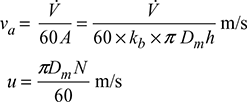
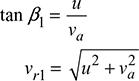
From the velocity triangle as shown in Fig. 15.4, we get


Power input/stage,


where ![]() and ηc = efficiency of the compressor
and ηc = efficiency of the compressor
Leave a Reply