In positive displacement type rotary compressors, the air is compressed by entrapping it between the reduced space of two sets of engaging surfaces. The pressure rise is either by backflow of air, as in the case of roots blower, or by both squeezing action and backflow of air, as in the case of vane type.
1 Roots Blower or Lobe Compressor
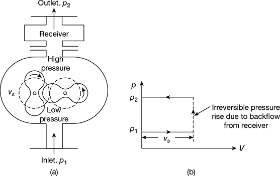
The schematic arrangement of a roots blower is shown in Fig. 13.1(a). It consists of two rotors that are driven externally. One rotor is connected to the driver and the second rotor is gear driven from the first in the opposite direction. The lobes of the rotors are of epicycloids, hypocycloid, or involute profiles to ensure a seal between the high and low pressure regions at all angular positions. A small clearance provided between the rotors and the cylinder surface to reduce the wear reduces the efficiency of the compressor due to leakage.
The volume Vs of air at atmospheric pressure p1 is entrapped between the left hand rotor and the cylinder casing. The volume of air once entrapped does not decrease from entry to exit, and therefore, there is no rise of pressure till the exit port is uncovered. As the exit part opens, some high pressure air from the receiver rushes back and mixes with the air volume Vs irreversibly until the pressure is equalised. The resulting pressure after mixing will be the receiver pressure p2. The air is then transferred to the receiver. This happens four times in one revolution in case of two-lobed rotor and six times in case of three-lobed rotor. The p−V diagram for the roots blower is shown in Fig. 13.1(b).

where i = number of lobes
Let V1 = volume of air handled per minute at p1 and T1.
Then work done per minute is,

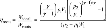
If the compression is isentropic, then ideal work required per minute is,
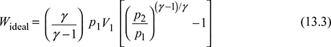
The efficiency of roots blower
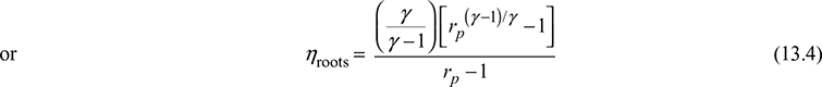
where rp = ![]() is the pressure ratio.
is the pressure ratio.
The roots blower is used to supply air from 0.15 to 1500 m3/min with pressure ratio up to 3.6 per blower. Rotational speeds up to 12,500 rpm are used and can be directly coupled to a steam turbine or a gas turbine shaft without any intermediate gearing.
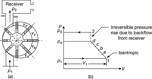
Figure 13.2 Vane type compressor
2 Vanes Type Blower
The schematic diagram of a vane type blower is shown in Fig. 13.2(a). It consists of a rotor located eccentrically in a cylindrical outer casing. The rotor carries a set of spring-loaded vanes in the slots of the rotor. The air of volume V1 at atmospheric pressure p1 is entrapped between two vanes. As the rotation proceeds counter clockwise, the entrapped air is first compressed reversibly to Va. Afterwards, the compression continues to Vc (say) and then to Vd. After this, the delivery port is uncovered and the irreversible compression takes place from pressure pd to p2. The p−V diagram for the compression process is shown in Fig. 13.2(b). The work done per revolution with i vanes is given by:
The vane blowers require less power than the root blowers for the same capacity and pressure rise. They are used to deliver up to 150 m3/min of air at pressure ratio up to 8.5. The speed is limited to 3000 rpm.
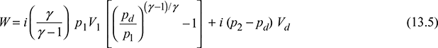
3 Lysholm Compressor
The Lysholm compressor is shown in Fig. 13.3. Its principle of working is similar to that of the roots blower. The air is admitted through one end of the compressor and trapped between the helical rotors and the casing. The screw action of the rotors displaces the air axially. It produces constant compression internally. Its main disadvantage is mechanical complexity.
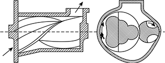
Figure 13.3 Lysholm compressor
4 Screw Compressor
The screw compressor may be single helical or double helical. The advantage of double helical is that they are balanced axially. The air is carried forward to the discharge along the rotor in pockets formed between the teeth and the casing as shown in Fig. 13.4. The principle of working is similar to that of the roots blower.
Figure 13.4 Screw compressor
Leave a Reply