1 Required Work
Without Clearance
Consider the theoretical p−V diagram for a single-stage air compressor as shown in Fig. 12.7. The work done on air per cycle is represented by the area 1–2–3–4–1.
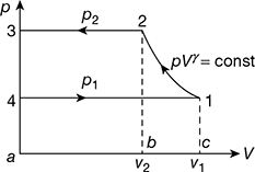
Figure 12.7 p-V diagram without clearance
W = area (a − b − 2 − 3 − a) + area (b − c − 1 − 2 − b) − area (a − c − 1 − 4 − a)
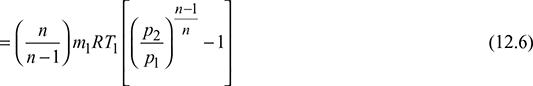
where m = mass of air delivered per cycle.
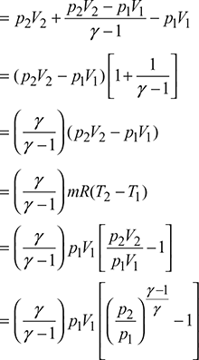
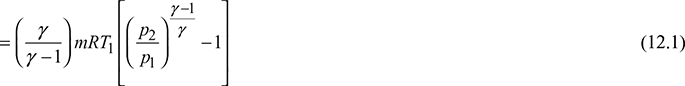
Work done per kg of air

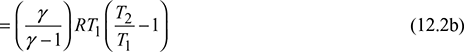
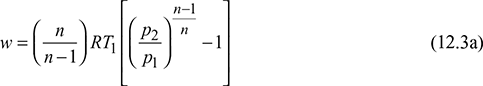
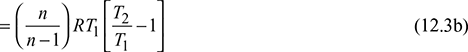
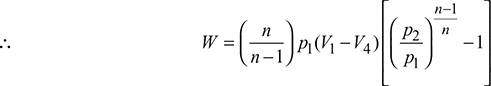
If the compression had followed the law, pVn = c, then
Power required in driving the compressor ![]()
where N = number of complete cycles per minute
= rpm, if single acting
= number of strokes per minute, if double acting.
With Clearance Volume
The p–V diagram for a single-stage and single-acting air compressor is shown in Fig. 12.8 with clearance volume.
Let Vc = clearance volume
Vs = swept volume = V1 − Vc
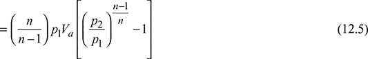
Va = actual volume = V1 − V4
Let the compression and expansion processes follow the same low pV n = const.
Work done per cycle,
W = area (1–2–3–4–1)
= area (1–2–5–6–1) − area (3–4–6–5–3)
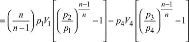
Now, p3 = p2 and p4 = p1
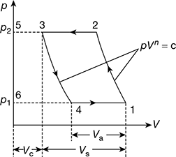
Figure 12.8 p-V diagram with clearance

Leave a Reply