An emission control programme aims at reducing the concentration of CO, HC, and NO. The main approaches adopted are as follows:
- Engine design modification: The following steps reduce the exhaust emission by engine design modification:
- Use leaner air-fuel ratio
- Retard ignition timing
- Avoid flame quenching time by reducing the surface to volume ratio of the combustion chamber
- Lower compression ratio
- Reduce valve overlap
- Modify the induction system by using high velocity carburettors or multi-chock carburettors
- Exhaust gas oxidation: The devices used to reduce HC/CO emissions are as follows:
- Use of after-burner
- Use of exhaust manifold reactor
- Use of catalytic converter
- Fuel modification: Air-fuel ratios leaner than stoichiometric result in almost insignificant amount of CO and reduce HC with reduced specific fuel consumption.
- Blow-by control: The crankcase blow-by control is the recirculation of the vapours back to the intake air cleaner.
To reduce atmospheric pollution, two different approaches are followed:
- Reduction of formation of pollutants in the emission by redesigning the engine system, fuel system, cooling system, and ignition system.
- Destroying the pollutants after these have been formed.
In petrol engines, the main pollutants which are objectionable and are to be reduced are HC, CO, and NOx. The methods used are as follows:
- Modifications in the engine design: Engine modifications improve emission quality. A few parameters which improve an emission are as follows:
- Combustion chamber configuration: Modification in the combustion chamber as reducing surface/volume ratio can reduce quenching zone and reduce HC emission. This can also be achieved by reducing dead space around piston ring.
- Lower compression ratio: Lower compression ratio also reduces the quenching area and thus reduces HC emission. Lower compression ratio also reduces NOx emission due to lower maximum temperature. However, lowering compression ratio reduces thermal efficiency and increases fuel consumption. By using petrol of lower octane number, it is possible to phase the lead out of petrol, that is, use of unleaded petrol.
- Induction system: The supply of designed A:F ratio mixture to multi-cylinder engine is always difficult under all operating conditions of load and power. This can be achieved by proper designing of induction system or using high velocity or multiple-choke carburettors.
- Ignition timing: Retarding spark ignition allows increased time for the fuel to burn. Retarding the spark reduces NOx formation by decreasing NOx emission. It also reduces HC emission by causing higher exhaust temperature. However, retarding the ignition results in loss of power and consumption of fuel. The controls are designed to retard the spark timing during idling and provide normal spark advance during acceleration.
- Reduced valve overlap: Increased overlap carries fresh mixture with the exhaust and increases emission level. This can be avoided by reducing the valve overlap.
- Modifying the fuel used: To reduce the pollution from the exhaust of these engines, the emission of olefins should be obviated as far as possible. For this, we can change the fuel itself. LPG and CNG be used instead of gasoline as they produce less pollution than present petrol engines.
- Exhaust gas treatment: Exhaust Gas Oxidation—The exhaust gases coming out of exhaust manifold are treated to reduce HC and CO emission. A few devices are discussed below.
- Use of after-burner: An after-burner is a burner where air is supplied to the exhaust gases and the mixture is burned with the help of an ignition system. The HC and CO which are formed in the engine combustion chamber because of inadequate O2 and inadequate time to burn are further burned by providing air in a separate box, known as an after-burner. The after-burner is located close to the exhaust manifold with an intention that the temperature of the exhaust should not fall. The oxidation of HC in the after-burner depends on the temperature of the exhaust and the mixing provided in the after-burner. Air injection does nothing to NOx emission. A simple arrangement of an after-burner is shown in Fig. 11.21.The performance of this system was not satisfactory as combustion was not sustained during low HC emission.
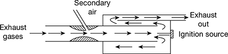 Figure 11.21 Typical after-burnerExhaust manifold reactor: This is a further development of the after-burner where high temperature exhaust gases and secondary air are mixed properly and burnt. Here HC carried with exhaust combines with O2 and forms non-objectionable gases.There are different types of after-burners where heat losses are minimised and sufficient time and mixing of exhaust and secondary air are provided.A special after-burner designed by Du-Point, where the entry of exhaust gases is radial and air flow is peripheral, is shown in Fig. 11.22.Catalytic converters: Catalytic oxidation of the exhausted HC and CO is accomplished by placing a common device called catalytic converter in the vehicle exhaust system. The catalytic converter is filled with catalytic material. Exhaust gas hydrocarbons and CO are oxidised while passing through the bed. The catalytic material itself does not enter into the reaction but only promotes the oxidation process at a lower temperature. Usually, air compressor is used to supply additional oxygen necessary for complete oxidation of the exhaust gas stream.A catalyst is an agent that aids or speeds a process or a chemical reaction without becoming a part of the reaction during the process—it is a sort of chemical middleman. In a modern car’s emissions control system, the so-called three-way catalyst helps the three major evil elements of exhaust—HC, CO, and NOx—react with oxygen and each other. The catalyst helps the HC and CO become non-poisonous CO2 and water vapour, whereas the NOx is converted into CO2, nitrogen, and water vapour.
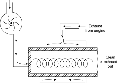 Figure 11.22 A typical after-burner
 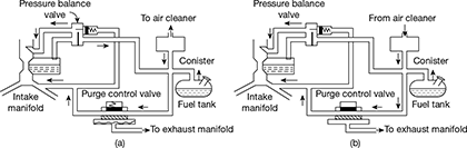 Figure 11.23 Fuel-system evaporation loss control device: (a) Hot soak condition, (b) Purging condition
 - Use of after-burner: An after-burner is a burner where air is supplied to the exhaust gases and the mixture is burned with the help of an ignition system. The HC and CO which are formed in the engine combustion chamber because of inadequate O2 and inadequate time to burn are further burned by providing air in a separate box, known as an after-burner. The after-burner is located close to the exhaust manifold with an intention that the temperature of the exhaust should not fall. The oxidation of HC in the after-burner depends on the temperature of the exhaust and the mixing provided in the after-burner. Air injection does nothing to NOx emission. A simple arrangement of an after-burner is shown in Fig. 11.21.The performance of this system was not satisfactory as combustion was not sustained during low HC emission.
- Evaporation Emission Control Device: The purpose of this device is to collect all evaporative emissions (vapours) and recirculating them at a proper time.The device is shown in Fig. 11.23. It consists of an absorbent chamber, pressure balancing valve, and purge control valve. The absorbent chamber contains charcoal which can hold the hydrocarbon vapour before it escapes into the atmosphere. The fuel tank and carburettor float, which are main sources of HC emission in the form of vapour, are directly connected to the absorbent chamber when the engine is turned off, that is, under hot soak-condition. This causes the petrol to boil from the carburettor float and a large amount of petrol vapour comes out. All these vapours during stopping or running the engine are absorbed in the absorber chamber.When the absorber bed becomes saturated, the air coming out from the air-cleaner is passed through the absorber bed and the air with vapour is passed to the inlet manifold through the purge valve. Here, the seat of the pressure balancing valve is so located that there is direct pressure communication between the internal vent and the top of the carburettor float, maintaining the designed carburettor metering forces.The operation of the purge control valve is controlled by the exhaust back pressure as shown in Fig. 11.23. The fuel supply is cut off under idling condition and the level of HC is reduced.
Leave a Reply