The power output of an engine depends on the amount of air inducted into the cylinder per unit time, the degree of utilisation of this air, and the thermal efficiency of the engine. The amount of air inducted per unit time can be increased by increasing the engine speed or by increasing the density of air at intake. The volumetric efficiency decreases as the speed is increased. The method of increasing the inlet air density is called supercharging. It is generally used to increase the power output of the engine. It is done by supplying air at a pressure higher than the pressure at which the engine naturally aspirates air from the atmosphere by using a pressure boosting device called a supercharger.
1 Thermodynamic Cycle
The p–v diagram for an ideal Otto-cycle supercharged engine is shown in Fig. 11.15(a). The pressure p1 represents the supercharging pressure and p6 is the exhaust pressure. Area 8-6-7-0-1-8 represents the work done by the supercharger in supplying air at a pressure p1, whereas the area 1-2-3-4-1 is the output of the engine. Area 0-1-6-7-0 represents the gain in work during the gas exchange process due to supercharging. Thus, a part of the supercharger work is recovered. However, the area 1-6-8-1 cannot be recovered and represents a loss of work. This loss of work causes the ideal thermal efficiency of the supercharged engine to decrease with an increase in supercharging pressure.
Figure 11.15(b) shows an ideal dual combustion cycle supercharged engine. The pressure p1 represents the supercharging pressure and p6 = p7, is the exhaust pressure. The engine is supercharged by the compressor. Area 9-10-1-11-9 represents the work done on the supercharger in supplying air at pressure p1. Thus, for the engine, 8-1 represents induction process, 1-2 as the compression process, 2-3-4 as the heat addition process, 4-5 as the expansion process, 5-6 as the blow down to atmosphere or heat rejection process and 6-7 as the exhaust process.
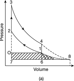
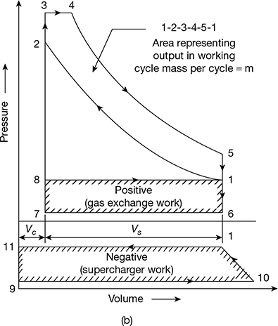
Figure 11.15 p-v diagram for supercharged engine: (a) Ideal Otto cycle, (b) Dual combustion cycle
Work done my mass m by the supercharged engine,
W = Area (1-2-3-4-5-1) + Area (8-1-6-7-8) — Area (9-10-1-11-9).
Thus, a part of the supercharger work is recovered; however, the curve equivalent to Area (9-10-1-11-9) — Area (8-1-6-7-8) is not recoverable and represents loss of work. This loss of work causes the ideal thermal efficiency of supercharged engine to decrease with an increase in supercharging pressure.
2 Supercharging of SI Engines
As far as SI engines are concerned, supercharging is employed only for aircraft and racing car engines. This is because the increase in supercharging pressure increases the tendency to detonate and pre-ignite.
Apart from increasing the volumetric efficiency of the engine, supercharging results in an increase in the intake temperature and pressure of the engine. These reduce the ignition delay and increase the flame speed and results in greater tendency to detonate or pre-ignite. For this reason, the supercharged SI engines use a lower compression ratio which results in lower thermal efficiency. The fuel consumption is also greater than naturally aspirated engines.
Due to its poor fuel economy, supercharging of petrol engines is not very popular and is used only when more power is needed or when more power is need to compensate altitude loss.
3 Supercharging of CI Engines
Supercharging of CI engines does not result in any combustion problems. Increase in pressure and temperature of the intake air reduces ignition delay and hence the rate of pressure rise results in a better, quieter, and smoother combustion. This allows the use of poor quality fuel. The increase in intake air temperature reduces volumetric and thermal efficiencies but the increase in density due to pressure compensates for this and intercooling is not required except for highly supercharged engines. It is possible to use lower fuel-air ratios in a supercharged engine, resulting in lower temperature and reduced smoke from the engine. This results in an increased life of the engine. Thus, a CI engine is more suitable for supercharging.
The apparatus used for increasing air density is known as a supercharger. A supercharger is an air compressor which may be positive displacement, reciprocating (piston-cylinder), rotary type (roots blower), or rotodynamic compressors (centrifugal or axial flow type). The centrifugal compressor is widely used as a supercharger for IC engines. The function of a supercharger is either to produce more power from an engine of a given cylinder size, or to compensate the power loss at high altitudes due to rarefied atmosphere.
4 Effects of Supercharging
The effect of supercharging on the power and efficiency is shown in Fig. 11.16.
- Power output: Supercharging produces more power because the supercharger supplies air at a pressure and density higher than atmospheric with has the effect of increasing volumetric efficiency.
- Mechanical efficiency: The mechanical efficiency of a supercharged engine is higher than that of one not supercharged.
- Fuel consumption: It provides better mixing of fuel and air, which results in a specific reduction of fuel consumption and the thermal efficiency increases.
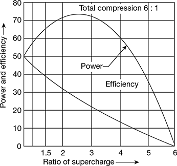
Figure 11.16 Effect of supercharging ratio on power and efficiency
5 Objectives of Supercharging
The objectives of supercharging are as follows:
- To overcome the effect of high altitudes, as in the case of aircrafts and stationary engines in mountains.
- To reduce the weight of an engine per kW or power developed, as in the case of racing cars.
- To reduce the size of the engine to fit into a limited space, as in the case of locomotives or marine engines.
- To increase the power output of an existing engine to meet greater power demands.
6 Configurations of a Supercharger
- Compressor Coupled of Engine Shaft: The compressor is operated directly by the engine with set-up gearing to increase the speed of centrifugal compressor. A part of the engine output is used to drive the supercharger and the net output is calculated by deducing this power from the gross power of the engine.
- Turbo-charger: The energy of the exhaust gases from the engine is used to develop power in a turbine which directly runs the supercharger. There is no mechanical connection between the engine and the supercharger.
- Direct Coupling between the Engine, Compressor, and Turbine: The advantage of this arrangement is that when the turbine output is insufficient to run the compressor, additional power required is taken from the engine. Additional power from the turbine can also be fed to the engine.
- Compressor geared with Engine and Free turbine: The engine drives the compressor but the energy in the exhaust is utilised to develop the power from a separate turbine.
The various configurations are shown in Fig. 11.17(a) to (d).
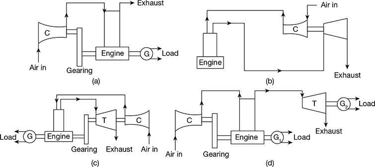
Figure 11.17 Arrangements for supercharging: (a) Mechanical supercharging, (b) Turbocharging, (c) Engine-driven compressor and turbocharger, (d) Engine-driven compressor and free turbine
7 Supercharging of Single Cylinder Engines
Supercharging of single cylinder engines is not carried out because the thermal efficiency drops to zero when the ratio of supercharger is about 6. Further, the power is maximum when the ratio of the supercharger is nearly 2, 5, and then drops to zero at a ratio of about 6.
Leave a Reply