For critical analysis, the performance of an IC engine under all conditions of load and speed is shown by a performance map. Figure 11.10 shows the performance map of an automotive SI engine and Fig. 11.11 shows the performance map of a four-stroke pre-chamber CI engine. Figure 11.11 also includes a typical curve of BMEP versus piston speed for level road operation in high gear. Note that these maps can be used for comparing engines of different sizes as performance parameters have been generalised by converting rpm into piston speed and brake power per time of piston area.
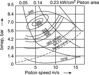
Figure 11.10 Form of performance map for a SI engine
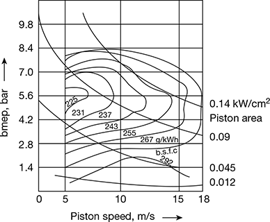
Figure 11.11 Form of performance map for a diesel engine
Generally, all engines show a region of the lowest specific fuel consumption (highest efficiency) at a relatively low piston speed with a relatively high BMEP.
SI Engine: Constant speed line: Increased BSFC is obtained by moving upward along the constant speed line because of mixture enrichment at high load which offsets an increase in mechanical efficiency. Moving to lower BMEP, the BSFC increases because of the reduced mechanical efficiency (IMEP decreases, whereas FMEP remains constant).
Constant BMEP line: Moving from the region of the highest efficiency along a line of constant BMEP, the BSFC increases due to increased friction at higher piston speeds. Moving to the left towards lower piston speed, although friction MEP decreases, indicated efficiency falls off owing to poor fuel distribution and increased relative heat losses.
CI Engine: In the CI engine, the BSFC increases at high loads owing to increased fuel waste (smoke) associated with high fuel-air ratios. At lower load, BSFC increases due to decrease in mechanical efficiency (same in the SI engine).
As speed is reduced from the point of the best economy along a line of constant BMEP, the product of mechanical and indicated thermal efficiency appears to remain about constant down to the lowest operating speed. The reduction in FMEP with speed is apparently balanced by a reduction in indicated thermal efficiency due to poor spray characteristics at very low speed.
An interesting feature of performance curves is that they show that power at maximum economy is about half of the maximum power.
Example 11.1
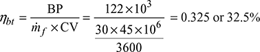
A six-cylinder, four-stroke spark-ignition engine of 10 cm × 2 cm (bore × stroke) with a compression ratio of 6 is tested at 4800 rpm on a dynamometer of arm 55 cm. During a 10 minutes test, the dynamometer reads 45 kg and the engine consumed 5 kg of petrol of calorific value 45 MJ/kg. The carburettor receives air at 9°C and 1 bar at the rate of 10 kg /min. Calculate (a) the brake power, (b) the brake mean effective pressure, (c) the brake specific fuel consumption, (d) the brake specific air consumption, (e) the brake thermal efficiency, and (f) the air-fuel-ratio.
Solution
Given that i = 6, n = 2, ∆ = 10 cm, L = 12 cm, r = 6, N = 4800 rpm, l = 55 cm, t = 10 min, w = 45 kg, mf = 5 kg, CV = 45 MJ/kg, ṁa = 10 kg /min
- Brake power,
 T = w × g × l = 45 × 9.81 × 55 × 10−2 = 242.79 N-m
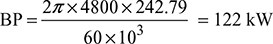
- BP = pbm [(LA)N/n] × Number of cylinders
 pbm = 5.39 bar

- ṁa = 10 kg /min or 600 kg /h

Example 11.2
A sharp-edged circular orifice of diameter 3.8 cm and coefficient of discharge as 0.6 is used to measure air-consumption of a four-stroke petrol engine. Pressure drop through the orifice is 145 mm of water and barometer reads 75.5 cm of Hg. The compression ratio of the engine is 6 and the piston displacement volume is 2000 cm3.
The temperature of air is taken to be 26°C. At 2600 rpm, the engine brake power recorded is 29.5 kW. The fuel consumption is 0.14 kg /min and the calorific value of fuel used is 43960 kJ/kg. Determine (a) the volumetric efficiency, (b) the air-fuel ratio, (c) the brake mean effective pressure, (d) the brake thermal efficiency, (e) the air standard efficiency, and (f) the relative efficiency.
Solution
Given that d = 3.8 cm, Cd = 0.6, hw = 14.5 cm of water, pa = 75.5 cm of Hg, r = 6, Vs = 2000 cm3, N = 2600 rpm, BP = 29.5 kW, ṁf = 0.14 kg /min, CV = 43960 kJ/kg
Density of air at atmospheric conditions,
Head in m of air = 
Velocity of air passing through orifice,
ca = [2gH]0.5 = [2 × 9.81 × 124.43]0.5 = 49.41 m /s
Volume of air passing through orifice,
= 0.033622 m3/s or 2.0173 m3/min
- Volumetric efficiency
- Mass flow rate of air,ṁa = Vaρa = 2.0173 × 1.1653 = 2.35 kg /min
- BMEP =
- Brake thermal efficiency
- Air standard efficiency,
- Relative efficiency =
Example 11.3
A four-stroke SI engine has six single-acting cylinders of 7.5 cm bore and 9 cm stroke. The engine is coupled to a brake having a torque arm radius of 38 m. At 3300 rpm, with all cylinders operating the net brake load is 324 N. When each cylinder, in turn, is rendered in operative, the average net brake load produced at the same speed of the remaining five cylinders is 245 N. Estimate the indicated mean effective pressure engine.
Solution
BP when all cylinders are working = ![]()
= 42.55 kW
BP when each cylinder is cut-off in turn
IP of cylinder cut off = 42.55 − 32.17 = 10.38 kW
Total IP of engine = 6 × 10.38 = 62.3 kW
Indicated mean effective pressure
Example 11.4
A six-cylinder SI engine operates in a four-stroke cycle. The bore of each cylinder is 70 mm and the stroke 100 mm. The clearance volume per cylinder is 67 cm3. At a speed of 3960 rpm the fuel consumption is 19.5 kg /h and the torque developed is 140 N-m. Calculate (a) brake power, (b) brake mean effective pressure, (c) the brake thermal efficiency if LCV of fuel is 44000 kJ/kg, and (d) the relative efficiency on brake power basis. Assume γ = 1.4 for air.
Solution
- Brake power
- Brake mean effective pressure
- Brake thermal efficiency
- Swept volume per cylinder,
 Compression ratio,
  Air standard efficiency,
  Relative efficiency,
Leave a Reply