The main metering system of a carburettor is designed to supply a nearly constant basis fuel-air ratio over a wide range of speeds and loads. This mixture corresponds approximately to best economy at full throttle (A/F ratio ≈ 15.6 or F/A ratio 0.064). Since a simple or elementary carburettor tends to enrich the mixture at higher speeds automatic compensating devices are incorporated in the main metering system to correct this tendency. These devices are as follows:
- Use of a compensating jet that allows an increasing flow of air through a fuel passage as the mixture flow increases.
- Use of emulsion tube for air bleeding. In this device, the emphasis is on air bleeding alone.
- Use of a tapered metering pin that is moved in and out of the main or auxiliary fuel orifice either manually or by means of some automatic mechanism changing the quantity of fuel drawn into the air charge.
- Back-suction control or pressure reduction in the float chamber.
- Changing the position or jet in the venturi. The suction action is highest at the venturi throat, therefore by raising the venturi the nozzle relatively moves to points with smaller suction and the flow of fuel is decreased.
- Use of an auxiliary air valve or port that automatically admits additional air as mixture flow increases.
The main devices are explained in detail.
- Compensating jet device: This device is shown in Fig. 10.23. In this device, in addition to the main jet, a compensating jet is provided which is in communication with a compensating well.The compensating well is open to atmosphere and gets its fuel supply from the float chamber through a restricting orifice. As the air flow increases, the level of fuel in the well decreases, thus reducing the fuel supply through the compensating jet. The compensating jet thus tends towards leanness as the main jet tends towards richness, the sum of the two remaining constant as shown in Fig. 10.25. At even higher rates of air flow, when the compensating jet has been emptied, air is bled through the compensating jet to continue the leanness effect, and incidentally, to assist in fuel atomisation.
- Emulsion tube or air bleeding device: In modern carburettors, the mixture correction is done only by air bleeding. In this arrangement, the main metering jet is fitted about 25 mm below the petrol level and it is called a submerged jet (see Fig. 10.26). The jet is situated at the bottom of a well, the sides of which have holes which are in communication with the atmosphere. Air is drawn through the holes in the well, the petrol is emulsified, and the pressure difference across the petrol column is not as great as that in the simple or elementary carburettor. Initially, the petrol in the well is at a level equal to that in the float chamber. On opening the throttle this petrol, being subject to the low throat pressure, is drawn into the air. This continues with decreasing mixture richness as the boles in the central tube are progressively uncovered. Normal flow takes place from the main jet.
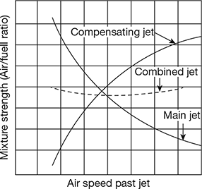 Figure 10.25 Variation of air-fuel ratio vs air flow with main and compensating jet
 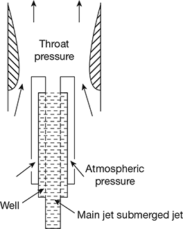 Figure 10.26 Correction in modern carburettors by air bleeding
 - Back-suction control or pressure reduction method: A common method of changing the air-fuel ratio in large carburettors is the back-suction control as shown in Fig. 10.27. In this arrangement, a relatively large vent line connects the carburettor entrance (say point 1) with the top of the float chamber. Another line, containing a very small orifice line, connects the top of the float chamber with the venturi throat (say point 2). A control valve is placed in the large vent line. When the valve is wide open, the vent line is unrestricted the pressure in the float chamber equal to p1, and the pressure difference acting on the fuel orifice is (p1 − p2). If the valve is closed, the float chamber communicates only with the venturi throat and the pressure on the fuel surface will be p2. Then ∆ pf will be zero, and no fuel will flow. By adjusting the control valve, any pressure between p1 and p2 may be obtained in the float chamber, thus changing the quantity of fuel discharged by the nozzle.
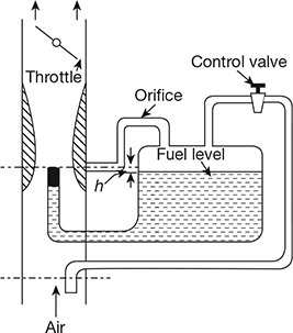 Figure 10.27 Back-suction control or pressure reduction method
 - Auxiliary valve carburettor: An auxiliary valve carburettor is illustrated in Fig. 10.28. With an increase of engine load, the vacuum at the venturi throat also increases. This causes the valve spring to lift the valve admitting additional air and the mixture is prevented from becoming over-rich.
- Auxiliary part carburettor: An auxiliary port carburettor is illustrated in Fig. 10.29. By opening the butterfly valve, additional air is admitted and at the same time the depression at the venturi throat is reduced, decreasing the quantity of fuel drawn in. This method is used in aircraft carburettors for altitude compensation.
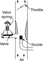 Figure 10.28 An auxiliary valve carburettor
 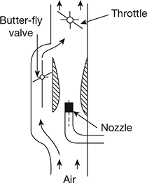 Figure 10.29 An auxiliary port carburettor
Leave a Reply