In SI engines, the air and fuel are mixed outside the engine cylinder and partly evaporated mixture is supplied to the engine. The process of preparing this mixture is called carburetion. The device used for this purpose is known as carburettor. The carburettor atomises the fuel and mixes it with air. This complicated process is achieved in the induction system, which is shown in Fig. 10.21. The pipe that carries the prepared mixture to the engine cylinder is called the intake manifold.
During the suction stroke, vacuum is created in the cylinder which causes the air to flow through the carburettor and the fuel to be sprayed from the fuel jets. Due to high volatility of the SI engine fuels, most of the fuel vaporises and forms a combustible fuel-air mixture. However, some of the larger droplets may reach the cylinder in the liquid form and must be vapourised and mixed with air during the compression stroke before ignition takes place by the electric spark.
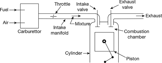
Figure 10.21 Induction system for SI engine
Table 10.5 F:A ratios for various running conditions of SI engines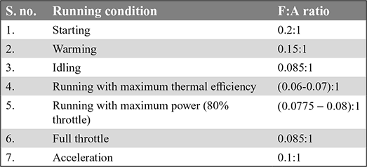
The fuel-air ratios for various running conditions of SI engines are given in Table 10.5.
1 Simple Carburettor
The details of a simple carburettor are shown in Fig. 10.22. It consists of a float chamber, fuel discharge nozzle and a metering orifice, a venturi, a throttle valve, and a choke. A float and a needle valve system maintains a constant level of gasoline in the float chamber. If the amount of fuel in the float chamber falls below the designed level, the float goes down, thereby opening the fuel supply valve and admitting fuel. When the designed level is reached, the float closes the fuel supply valve, thus stopping additional fuel flow from the supply valve and stopping additional fuel flow from the supply system. The float chamber is vented either to the atmosphere or to the upstream side of the venturi.
During suction stroke, air is drawn through the venturi (or choke tube). As the air passes through the venturi, the velocity increases, reaching a maximum at the venturi throat and pressure decreases to a minimum. From the float chamber, the fuel is fed to a discharge jet, the tip of which is located in the throat of the venturi, fuel is discharged into the air stream. To avoid overflow of fuel through the jet, the level of the liquid in the float chamber is maintained at a level slightly below the tip of the discharge jet.
The throttle valve controls the amount of charge delivered to the cylinder, which is situated after the venturi tube. As the throttle is closed, less air flows through the venturi tube and less quantity of the air-fuel mixture is delivered to the cylinder; hence, the power output is reduced. The reverse takes place when the throttle is opened.
2 Compensating Jet
The function of the compensating jet is to make the mixture leaner as the throttle opens progressively. As shown in Fig. 10.23, the compensating jet is connected to the compensating well which is vented to the atmosphere. The compensating well is supplied with fuel from the main float chamber through a restricting orifice. With the increase in air flow rate, there is a decrease in the fuel level in the compensating well, with the result that fuel supply through the compensating jet decreases. The compensating jet, thus, progressively makes the mixture leaner as the main jet progressively makes the mixture richer.
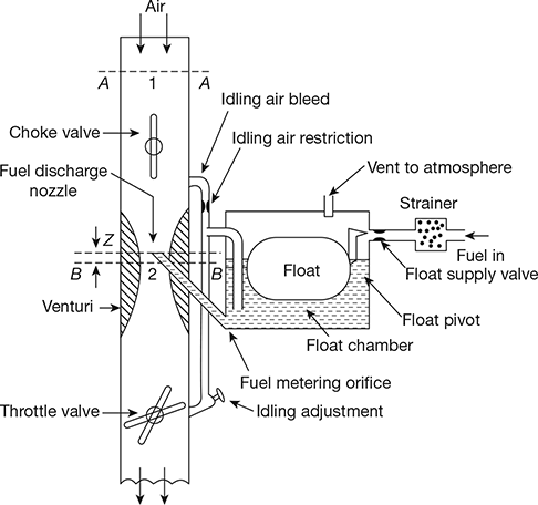
Figure 10.22 Simple carburettor
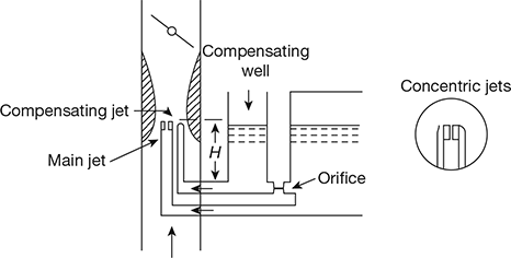
Figure 10.23 A compensating jet device
3 Theory of Simple Carburettor
The air from the atmosphere is sucked through the carburettor by the pressure difference across it created when the piston moves on its suction stroke. The velocity of the air increases as it passes through the venturi and reaches maximum at venturi throat (Fig. 10.24). The pressure also changes and is maximum at section 2-2, because this is the minimum area in the induction track. The fuel is sucked through the nozzle because of suction created in the venturi.
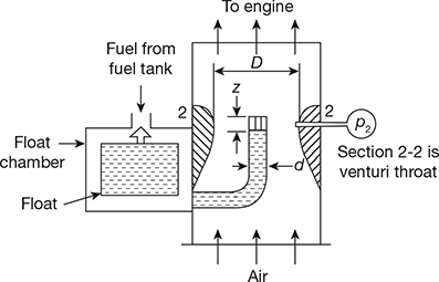
Figure 10.24 Principles of a simple carburettor
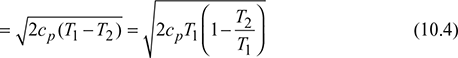
- Approximate analysis (neglecting compressibility of air): Let z be the height in metre of fuel nozzle tip higher than the float chamber level. Assuming initial velocity of air to be negligible (c1 = 0), density of air to be constant and considering sections at entrance and venturi throat, by applying, Bernoulli’s theorem, we get
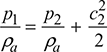 where p1, p2 = pressure at sections 1 and 2, respectively, N/m2c2 = velocity of air at section 2, m/sρa = density of air, kg/m3
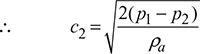 Mass of air per second,
 where A2 = area of venturi throat, m2Similarly, for the flow of fuel, we have
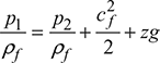 where ρf = constant density of fuel, kg/m3cf = velocity of flow of fuel, m/s
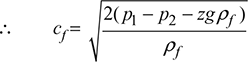 Mass flow rate of fuel,
 where Af = cross-sectional area of fuel nozzle, m2
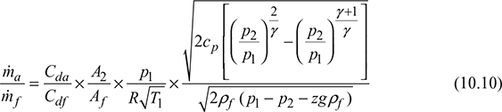
 Taking the coefficient of discharge of fuel nozzle and venturi into account, we have
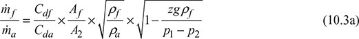 where Cd = coefficient of discharge.If z = 0.
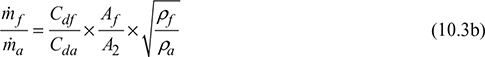
- Exact analysis: Considering compressibility of air and applying steady flow energy equation to sections 1 and 2, we get
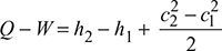 where h1, h2 = enthalpies at sections 1 and 2 respectivelySince Q = 0, W = 0 and c1 = 0
 For isentropic flow between the atmosphere and venturi throat, we have
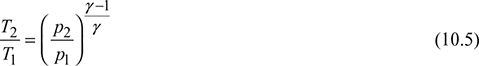
 where v = specific volumeSince
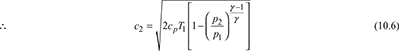
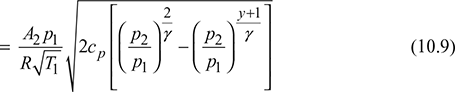
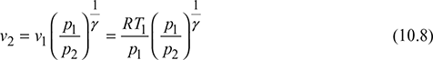 Eq. (10.7) becomes
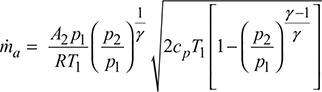
4 Limitations of Single Jet Carburettor
The drawbacks of single jet carburettor are as follows:
- A single jet carburettor cannot provide a very rich mixture as required at the time of starting the engine. This is because at low speed (starting or idling), the pressure difference causing the fuel flow is very small as the throttle is nearly closed. It is not possible to discharge fuel to make the mixture considerably rich.
- It cannot provide a very rich mixture required for sudden acceleration of the engine.
- For gradually increasing pressure difference over the jet (at higher speed of the engine), the weight of the petrol discharged from a single jet increases at a greater rate than does the air supply. Hence, a single jet carburettor gives a progressively richer mixture as the air speed increases when set to given a correct mixture at low air speeds.
- It cannot reduce the quantity of air flow during starting as required in cold weather conditions.
- The automatic control of air and fuel according to the required conditions is not possible.
The carburettor used with a variable speed engine must fulfil all the following requirements:
- It must atomise the fuel and mix it homogeneously with the air.
- It must be able to run the engine smoothly without hunting or fuel wastage.
- It must provide rich mixture during starting and idling.
- It must provide a constant air-fuel ratio during normal running of the engine which is the maximum period.
- It must provide a rich mixture required for quick acceleration of the engine.
- It must be able to start the engine even in very cold weather conditions (during snowfall).
- All operations should be automatic.
To fulfil the above requirements, the following devices are introduced.
- A starting or a pilot jet (to start engine)
- Compensating devices (to provide constant A:F ratio during normal operation conditions)
- An automatic control of choke valve (to start the engine in cold weather)
5 Different Devices Used to Meet the Requirements of an Ideal Carburettor
The main function of the carburettor is to vapourise the petrol in the current of air created by means of engine suction and supply the required quantity of air and petrol mixture in proper proportion in accordance with the load on the engine and its speed.
In the design of a carburettor, the following points should be considered:
- It is seen that for a gradually increasing pressure difference over the fuel jet, the mass of petrol discharged from a single jet increases at a greater rate than does the air supply. Hence, a carburettor of this type will give a progressively rich mixture as air speed is increased. There must be some device to maintain A: F ratio constant over a wide range of engine speed.
- To ensure rapid and complete combustion, it is necessary that the fuel should be finely divided and intimately mixed with air supply. This can be done by proper design of venturi and inlet manifold.
- For starting and accelerating, a rich mixture must be supplied momentarily but the supply should come to the correct mixture strength automatically when the engine attains the desired speed.
- There must be a provision to supply extra-rich mixture to start the engine in a very cold weather (where temperature falls to zero or sub-zero temperature).
- The float in the float chamber of a carburettor must maintain the fuel level constant irrespective of load or speed of the engine.
6 Complete Carburettor
In order to satisfy the demands of an engine under all conditions of operations, the following additional systems are added to the simple carburettor:
- Main metering system
- Idling system
- Power enrichment by economiszer system
- Acceleration pump systems
- Choke.
Leave a Reply