1 Four-stroke Petrol Engine
The theoretical and actual p-v diagrams for a four-stroke petrol engine are shown in Figs. 10.16(a) and (b), respectively.
The theoretical p–v diagram is drawn with the following assumptions:
- Suction and exhaust take place at atmospheric pressure through 180° rotation of crank.
- Compression and expansion take place through 180° rotation of crank.
- Compression and expansion processes are isentropic.
- The combustion takes place instantaneously at constant volume at the end of compression stroke.
- Pressure suddenly falls to the atmospheric pressure at the end of expansion stroke.
The various processes of theoretical p-v diagram are as follows:
5-1: Suction stroke (pa = const)
1-2: Compression stroke (pvγ = const)
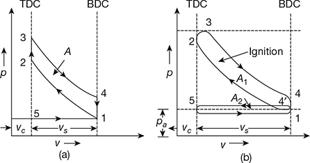
Figure 10.16 Theoretical and actual p-v diagrams for a four-stroke petrol engine: (a) Theoretical, (b) Actual
2-3: Instantaneous combustion (v = const)
3-4: Expansion stroke (pvγ = const)
4-1: Sudden fall in pressure (v = const)
1-5: Exhaust stroke (pa = const)
In practice, the actual conditions differ from the ideal as follows:
- The suction of mixture in the cylinder is possible only if the pressure inside the cylinder is below atmospheric pressure.
- The burnt gases can be pushed out into the atmosphere only if the pressure of the exhaust gases is above atmospheric pressure.
- The compression and expansion do not follow the isentropic law, as there will be heat exchange during these processes.
- Sudden pressure rise is not possible after the ignition as combustion takes some time for completion and actual pressure rise is less than theoretical considered. The pressure increase takes place through some crank rotation, or increase in volume.
- Sudden pressure release after the opening of expansion valve is not possible and it also takes place through some crank rotation.
If all these modifications are taken into account, then the cycle can be represented on p–v diagrams as shown in Fig. 10.16(b).
The area 4′-5-1-4′ representing negative work is called negative loop or pumping loop. This work is required for admitting the fresh charge and for exhausting the burnt gases. This loss of work is known as pumping loss and power consumed for this is known as pumping power.
The net work per cycle of the engine is given by the area (A1 − A2). This area (A1 − A2) is always less than the area A as shown in Fig. 10.16(a) due to the actual deviations of operations from the theoretical ones.
If both the areas are represented in the form of rectangles taking vs as base, then the ordinates give the mean effective pressures as shown in Fig. 10.17.
pma (Actual mean effective pressure) = pmt (theoretical mean effective pressure) × DF (diagram factor)
2 Four-stroke Diesel Engine
The theoretical and actual p-v diagrams for a four-stroke diesel engine are shown in Figs. 10.18(a) and (b), respectively.
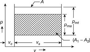
Figure 10.17 p-v diagrams
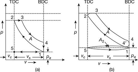
Figure 10.18 Theoretical and actual p-v diagrams for a four-stroke diesel engine: (a) Theoretical, (b) Actual
The theoretical p-v diagram for a four-stroke diesel engine is drawn with the following assumptions:
- Suction and exhaust take place at atmospheric pressure through 180° of crank rotation.
- Compression and expansion take place during 180° of crank rotation.
- Compression and expansion are isentropic.
- The combustion takes place at constant pressure during a small part of expansion stroke.
- Pressure suddenly falls to atmospheric pressure at the end of expansion stroke.
With the above assumptions, the working cycle can be represented on a p–v diagram as shown in Fig. 10.18(a), and it is similar to the theoretical diesel cycle. The various processes of theoretical p–v diagram are as follows:
5-1: Suction stroke (pa = const)
1-2: Compression stroke (pvγ = const)
2-3: Constant pressure combustion (p = const)
3-4: Expansion stroke (pvγ = const)
4-1: Sudden fall in pressure (v = const)
1-5: Exhaust stroke (pa = const)
However, in practice, the actual conditions differ from the ideal described as follows:
- The suction of the air inside the cylinder is possible only if the pressure inside the cylinder is below atmospheric.
- Exhausting of gasses is possible only if the pressure of the exhaust gases is above atmospheric pressure.
- The compression and expansion do not follow the isentropic process, as there are heat and pressure losses.
- The combustion at constant pressure is not possible as the fuel will not burn as it is introduced into the cylinder.
- The sudden pressure release after the opening of expansion valve is not possible and it takes place through some crank rotation.
The operations of the cycle, taking the modifications into account, are represented on the p–v diagram in Fig. 10.18(b). Actual area (A1 − A2) on p–v diagram per cycle is less than theoretical.
3 Two-stroke Petrol Engine
The theoretical and actual p–v diagrams for a two-stroke petrol engine are shown in Fig. 10.19. The following assumptions are made for drawing the theoretical p–v diagram:
- The expansion during power stroke and compression during compression stroke are isentropic.
- The combustion takes place instantaneously at constant volume at the end of compression.
- The pressure falls instantaneously to the atmospheric pressure as the piston uncovers the exhaust ports during power stroke.
- The scavenging takes place at atmospheric pressure.
It may be observed from Fig. 10.19(a) that the compression of the charge starts from ‘1’ instead of point 6.
Effective compression ratio,

where vse = effective stroke volume = ![]()
vsa = actual stroke volume = ![]()
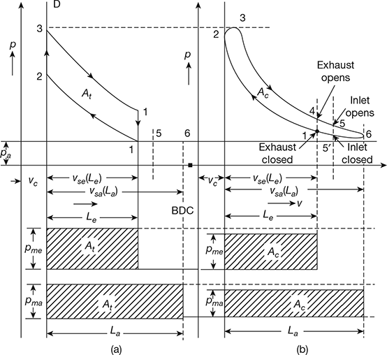
Figure 10.19 Theoretical and actual p-v diagrams for a two-stroke petrol engine: (a) Theoretical, (b) Actual
Le, La = effective and actual stroke lengths, respectively
d = cylinder diameter
The various processes are as follows:
1-2: isentropic compression (pvγ = c)
2-3: instantaneous combustion (v = c)
3-4: isentropic expansion (pvγ = c)
4-1: release of burned charge to atmosphere (v = c)
1-6 and 6-1: sweeping out of exhaust gases to atmosphere
Point 5: inlet port opens
5-6 and 6-5: charging the cylinder with fresh charge and scavenging action. Actual theoretical mean effective pressure,
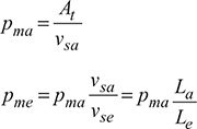
pma, pme = actual mep on the basis of actual and effective stroke respectively. In practice, the actual conditions differ from the ideal as described below:
- The compression and expansion processes do not follow the isentropic law strictly.
- Instantaneous combustion at the end of compression is not possible. The actual pressure rise takes place through some crank angle, resulting in rounding of the diagram.
- The scavenging always takes place above atmospheric pressure.
- Instantaneous fall of pressure at the time of release is not possible.
4 Two-stroke Diesel Engine
The theoretical and actual p-v diagrams for a two-stroke diesel engine are shown in Fig. 10.20. The various processes are as follows:
1-2: isentropic compression (pvy = c)
2-3: instantaneous combustion (p = c)
3-4: isentropic expansion (pvy = c)
4-1: release of burned charge to atmosphere (v = c)
1-6 and 6-1: sweeping out of exhaust gases to atmosphere
5-6 and 6-5: charging the cylinder with fresh charge and scavenging action.
Point 5: inlet port opens.
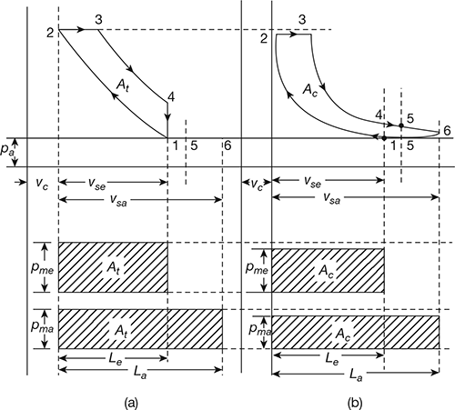
Figure 10.20 Theoretical and actual p-v diagrams for a two-stroke diesel engine: (a) Theoretical, (b) Actual
Leave a Reply