- Low level counter-flow jet condenser: This type of condenser is shown in Fig. 8.3. The cold water is drawn up in the condenser shell from the cooling pond due to the vacuum head created in the shell. The level of the cooling pond should not be much below the delivery pipe to the shell as no pump is used. The shell is arranged with two or three water trays with perforations to break up water into small jets. The exhaust steam and any mixed air enters at lower portion of the shell and tries to ascend up through the falling sprays. Thus, steam gets condensed and air ascends up and cools down. The air is removed by a separate suction pump at the top. The mixture of condensate and cooling water descends down through a vertical pipe to the extraction pump and pumped to the hot well. From the hot well, the boiler feed pump delivers water to the boiler and surplus water overflows to the cooling pond. Since the boiler feed and the cool injection water mix, this type of condenser may be used only where cheap pure water is available. The non-condensable air and gas are continuously removed by air pump suction to maintain vacuum.
- Low level parallel flow Jet condenser: It is similar to the counter flow jet condenser except that steam enters the condenser shell at the top and just below it the cooling water is delivered. It is less efficient than the counter flow type.
- High level jet condenser: This is also called Barometric condenser and is shown in Fig. 8.4. The shell is placed at a height greater than 10.363 m, the barometric height of water column. If a pipe of height more than 10.363 m is held vertical with one end immersed in water vessel open to atmosphere and the other end subjected to suction pressure, the atmospheric pressure will hold the column of water in the pipe equal to the suction pressure. This fact is made use of in this condenser by making the tail pipe more than 10.363 m in height and thus making it impossible for any vacuum in the condenser to cause the water to rise high in the tail pipe of the water leg and flood the engine.
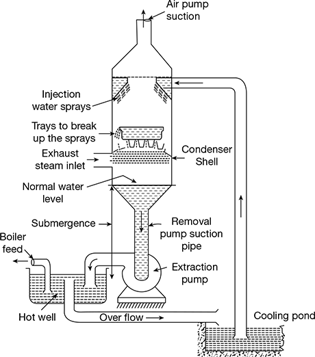 Figure 8.3 Low level counter flow jet condenser
  Figure 8.4 High-level jet condenser
  Figure 8.5 Ejector condenserThe height of the shell much above the barometric height requires a separate pump for injecting cool water. The condensate and water will fall under gravity to the hot well and maintain a column of water in the water leg, depending on the vacuum in the condenser. A separate air pump to remove air is employed.
 - Ejector condenser: It is a low-level type of condenser (as shown in Fig. 8.5). This condenser works on the principle that by discharging a smooth jet of cold water under a head of about 6 m through a series of converging guide cones, the steam and the associated air are drawn in through the hollow truncated cones and led to the diverging cones. In the converging cones, the pressure energy is partly converted to kinetic energy. In the diverging cones, the kinetic energy is again partly converted to pressure energy so as to obtain pressure greater than the atmospheric to enable the condensate and water mixture to be discharged to the hot well exposed to atmospheric pressure.A non-return valve is fitted on the exhaust steam inlet to condenser so that water from the hot well does not rush back to the engine in case of cold injected water failure.
2 Surface Condensers
Water Tube Surface Condenser
In this type of surface condenser, water flows in the tubes and steam surrounds it. Thus, the condensate is directly available as an ideal boiler feed. A surface condenser produces more vacuum and any type of cooling water can be used. However, it is bulky and the initial capital cost is higher than jet condensers. But, this is justified by the saving in the running cost due to high efficiency.
This type of condensers may be further classified as follows:
- Single pass, two pass condensers
- Down flow: central flow regenerative condensers
A longitudinal section of a two pass, down flow condenser is shown in Fig. 8.6. It consists of a cast iron shell, cylindrical in shape, with the two ends covered by cover plates. A nest of brass tubes is fixed in the two tube plates at the end. They are fixed by brass ferrules so that they can be replaced easily.The space between the tube plates and the cover plates is known as water boxes. One of the water boxes has baffle partitioning the box into two sections—one upper half and the other lower half.
The cold water is sent through the lower half section tubes and comes out through the upper half section tubes. Exhaust steam enters the shell at the top and flows down surrounding the cold water tubes. The condensate is removed at the bottom by an extraction pump.
The surface condensers may work on the wet vacuum system or the dry vacuum system. For the dry vacuum system, three pumps are required—one for the circulating cooling water, the other for removing the condensate, and the third, the dry air pump, for removing air. The cross-section of such a dry vacuum system is shown in Fig. 8.7. The air exit is shielded from the down flow of steam by means of a baffle.
The main requirements of a surface condenser are as follows:
- Air should be removed at a cooler section and it should be as far as possible dry.
- The pressure drop of steam in the condenser should be minimum.
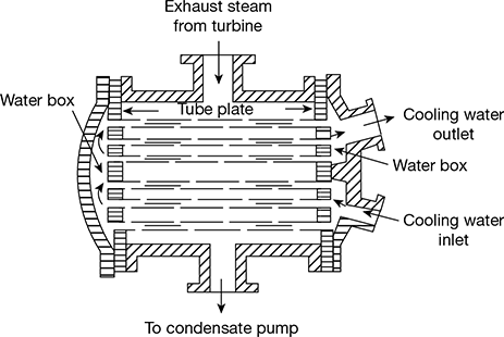
Figure 8.6 Water tube surface condenser

Figure 8.7 Down flow surface condenser
Leave a Reply