The steam turbine blades are subjected to high pressure and temperature. In the intermediate pressure stages, the steam is wet. Therefore, the material of blades should be able to withstand corrosion and erosion due to the presence of water particles. In addition to corrosion and erosion, blades are subjected to high centrifugal stresses. When the speed is high and the dryness fraction is less than 0.9, the effect of moisture is the most prominent. The most affected position is the back of the inlet edge of the blade, where either grooves are formed or even some portion breaks away. Due to centrifugal force, the water particles tend to concentrate in the outer annulus and their tip speed is greater than the root speed. Hence, erosion effect is the most prominent on the tips, as shown in Fig. 7.33.
The following methods may be adopted to prevent erosion:
- By raising the temperature of steam at inlet so that at the exit of the turbine, the dryness fraction does not fall below 0.9.
- By adopting reheat cycle so that the dryness fraction at exit remains within limits.
- By providing drainage belts on the turbine so that the water droplets which are on outer periphery, due to centrifugal force, are drained.
- By providing a shield of a hard material on the leading edge of the turbine.
The most satisfactory solution to prolong the blade life is providing tungsten shield.
Example 7.12
In a De-Laval turbine, steam enters the wheel through a nozzle with a velocity of 500 m/s and at an angle of 20° to the direction of motion of the blade. The blade speed is 200 m/s and the exit angle of the moving blade is 25°. Find the inlet angle of the moving blade, exit velocity of steam and its direction and work done per kg of steam.
Solution
Given that va1 = 500 m/s; α1 = 20°; u = 200 m/s; β2 = 20°, vr2 = vr1.
Now let us draw the combined velocity triangles, as shown in Fig. 7.34, as explained below:
- First, draw a horizontal line and cut off AB equal to 200 m/s, to some suitable scale, representing the blade speed, u.
- Now at B, draw a line BC at an angle of 20° (nozzle angle, α1) and cut off BC equal to 500 m/s to the same scale to represent the velocity of steam jet entering the blade (va1).
- Join AC, which represents the relative velocity at inlet (vr1).
- At A, draw a line AD at an angle of 25° (exit angle of the moving blade, β2). Now with A as centre, and radius equal to AC, draw an arc meeting the line through A at D.
 Figure 7.34 Velocity diagrams for De-Laval steam turbine
 - Join BD, which represent the velocity of steam jet at outlet (va2).
- From C and D, draw perpendiculars meeting the line AB produced at E and F respectively. CE and DF represent the velocity of flow at inlet (vf 1) and outlet (vf 2) respectively.
The following values are measured from the velocity diagram:
β1 = 32°, α2 = 59°; va2 = BD = 165 m/s
vw1 = BE = 470 m/s and vw2 = BF = 90 m/s
By measurement from the velocity diagram, the inlet angle of the moving blade, β1 = 32°
By measurement from the velocity diagram, the exit velocity of steam, va2 = 165 m/s
By measurement from the velocity diagram, the direction of the exit steam, α2 = 59°
Work done per kg of steam = ṁ (vw1 + vw2)
= 1 (470 + 90) = 560 N-m/kg ∵(ṁ = 1 kg)
Example 7.13
The velocity of steam leaving the nozzles of an impulse turbine is 1200 m/s and the nozzle angle is 20°. The blade velocity is 375 m/s and the blade velocity coefficient is 0.75. Assuming no loss due to shock at inlet, calculate for mass flow of 0.5 kg/s and symmetrical blading: (a) blade inlet angle; (b) driving force on the wheel; (c) axial thrust on the wheel; and (d) power developed by the turbine.
Solution
Given that va1 = 1200 m/s; α1 = 20°; u = 375 m/s; K = vr2/vr1 = 0.75; ṁ = 0.5 kg/s; β1 = β2, for symmetrical blading.
Now draw the combined velocity triangle, as shown in Fig. 7.35, as explained below:
- First, draw a horizontal line, and cut off AB equal to 375 m/s to some suitable scale representing the velocity of blade(u).
- Now at B, draw a line BC at an angle of 20° (Nozzle angle, α1) and cut off BC equal to 1200 m/s to the scale to represent the velocity of steam jet entering the blade (va1).
 Figure 7.35 Velocity diagrams for impulse turbine
 - Join CA, which represents the relative velocity at inlet (vr1). By measurement, we find that CA = vr1 = 860 m/s. Now cut off AX equal to vr2 = vr1 × K = 860 × 0.75 = 645 m/s to the scale to represent the relative velocity at exit (vr2).
- At A, draw a line AD at an angle β2 equal to the angle β1, for symmetrical blading. Now with A as centre, and radius equal to AX, draw an arc meeting the line through A at D, such that AD = vr2.
- Join BD, which represents the velocity of steam jet at outlet (va2).
- From C and D, draw perpendiculars meeting the line AB produced at E and F respectively. CE and DF represents the velocity of flow at inlet (vf 1) and outlet (vf 2), respectively.
The following values are measured from the velocity diagram:
β1 = 29°, vw1 = BE = 1130 m/s; vw2 = BF = 190 m/s
vf1 = CE = 410 m/s and vf2 = DF = 310 m/s.
- By measurement from the velocity diagram, the blade angle at inlet, β1 = 29°
- Driving force on the wheel, Fx = m (vw1 + vw2) = 0.5 (1130 + 190) = 660 N
- Axial thrust on the wheel, Fy = m (vf 1 − vf 2) = 0.5 (410 − 310) = 50 N
- Power developed by the turbine,
P = ṁ (vw1 + vw2) u = 0.5 (1130 + 190) 375 = 247500 W or 247.5 kW
Example 7.14
A single row impulse turbine receives 3 kg/s steam with a velocity of 425 m/s. The ratio of blade speed to jet speed is 0.4 and the stage output is 170 kW. If the internal losses due to disc friction etc., amount to 15 kW, determine the blade efficiency and the blade velocity coefficient. The nozzle angle is 16° and the blade exit angle is 17°.
Solution
Given that ṁ = 3 kg/s; va1 = 425 m/s; u/va1 = 0.4; stage output = 170 kW; internal losses = 15 kW; α1 = 16°; β2 = 17°.

Figure 7.36 Velocity diagrams for single row impulse turbine
- Blade speed, u = va1 × 0.4 = 425 × 0.4 = 170 m/sTotal power developed, P = Stage output + Internal losses= 170 + 15 = 185 kWLet vw1 + vw2 = Change in the velocity of whirlPower developed, P = ṁ (vw1 + vw2) u185 × 103 = 3 (vw1 + vw2) 170∴ vw1 + vw2 = 363 m/sNow, draw the combined velocity triangle, as shown in Fig. 7.36, and explained below:
- First, draw a horizontal line and cut off AB equal to 170 m/s, to some suitable scale, to represent the blade speed (u).Now, draw the inlet velocity triangle ABC on the base AB with α1 = 16° and va1 = 425 m/s, to the scale, chosen.Similarly, draw the outlet velocity triangle ABD on the same base AB with β2 = 17° and (vw1 + vw2) = 363 m/s to the scale.From C and D, draw perpendiculars to meet the line AB at E and F. From the geometry of the figure, we find that vw2 is in the opposite direction of vw1. Therefore, (vw1 − vw2) = 363 m/s.

- Blade velocity coefficient,

Example 7.15
In one stage of a reaction steam turbine, both the fixed and moving blades have inlet and outlet blade tip angles of 35° and 20°, respectively. The mean blade speed is 80 m/s and the steam consumption is 22500 kg per hour. Determine the power developed in the pair, if the isentropic heat drop for the pair is 23.5 kJ per kg.

Figure 7.37 Velocity diagrams for reaction turbine
Solution
Given that β1 = α2 = 35°; β2 = α1 = 20°; u = 80 m/s; ṁ = 22500 kg/h = 6.25 kg/s; Δh = 23.5 kJ/kg.
Now, let us draw the combined velocity triangle, as shown in Fig. 7.37 and explained below:
- First, draw a horizontal line and cut off AB equal to 80 m/s (u) to some suitable scale.
- Now at B, draw in line BC at an angle α1 = 20° with AB. Similarly, at A draw a line AC at an angle β1 = 35° with BA meeting the first line at C.
- At A, draw a line AD at angle β2 = 20° (because β2 = α1) with AB. Similarly, at B draw a line BD at an angle α2 = 35° (because α2 = β1) with AB meeting the first line at D.
- From C and D, draw perpendiculars meeting the line AB produced at E and F.
By measurement, we find that the change in the velocity of whirl,
Δw = vw1 + vw2 = 235 m/s
Power developed in the pair,
P = ṁ (vw1 + vw2) u = 6.25 × 235 × 80 = 117500 W = 117.5 kW
Example 7.16
A 50% reaction turbine with a mean blade diameter of 1 m runs at a speed of 50 rps. The blades are designed with exit angles of 50° and inlet angles of 30°. If the turbine is supplied with steam at the rate of 20 kg/s and gross efficiency is 85%, determine the following: (a) power output of the stage; (b) specific enthalpy drop in the stage; and (c) percentage increase in relative velocity in the moving blades due to steam expansion.
Solution
Given that dm = 1 m; N = 50 rps; β1 = α2 = 50°; β2 = α1 = 30°; m = 20 kg/s; ηs = 85%
- Blade velocity, u = π dm N = π × 1 × 50 = 157 m/sNow let us draw the combined velocity triangle, as shown in Fig. 7.38, and explained below:
- First, draw a horizontal line and cut off AB equal to 157 m/s, to some suitable scale, to represent the blade velocity u.Now, draw the inlet velocity triangle ABC on the base AB with α1 = 30° and β1 = 50°.Similarly, draw the outlet velocity triangle ABD on the same base AB with β2 = 30° and α2 = 50°.From C and D, draw perpendiculars to meet the line AB produced at E and F.
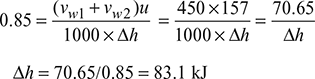
 Figure 7.38 Velocity diagrams for symmetrical blades reaction turbineand relative velocity at outlet, vr2 = DA = 350 m/sPower output of the stage,P = ṁ (vw1 + vw2) u = 20 × 450 × 157 = 1413000 W = 1413 kW.
 - Let Δh = specific enthalpy drop in the stage.We know that stage efficiency (ηs);
- Increase in the relative velocity in the moving blades due to steam expansion.

Example 7.17
At a stage of a 50% reaction turbine, the rotor diameter is 1.4 m and speed ratio 0.7. If the blade outlet angle is 20° and the rotor speed 3000 rpm, find the blade inlet angle and diagram efficiency.
Find the percentage increase in diagram efficiency and rotor speed, if the turbine is designed to run at the best theoretical speed.
Solution
Given that D = 1.4 m; ρ = u/va1 = 0.7; α1 = β2 = 20°; N = 3000 rpm.
Blade velocity,

and velocity of steam at inlet to the blade.
va1 = u/0.7 = 220/0.7 = 314.3 m/s
Now draw the combined velocity triangle, as shown in Fig. 7.39, as explained below:
- First, draw a horizontal line and cut off AB equal to 220 m/s, to some suitable scale, to represent the blade velocity (u).
 Figure 7.39 Velocity diagrams for reaction turbine with Rd = 50%
 - Now, draw the inlet velocity triangle ABD on the same base AB with α1 = 20° and va1 = 314.3 m/s, to the scale.
- Similarly, draw the outlet velocity triangle ABD on the same base AB with β2 = 20° and vr2 = 314.3 m/s to the scale.
- From C and D, draw perpendiculars to meet the line AB produced at E and F.
By measurement from velocity diagram, we find that the blade inlet angle.
β1 = 55°
By measurement from velocity diagram, we find that velocity of steam at outlet,
va2 = 130 m/s
Diagram efficiency,

Maximum efficiency of the turbine,

∴ Percentage increase in diagram efficiency = ![]() = 0.131 or 13.1%
= 0.131 or 13.1%
Let N1 = Maximum rotor speed.
For best theoretical speed (or in other words, for maximum efficiency), the blade velocity,
u = va1 cos α1 = 314.3 cos 20° = 314.3 × 0.9397 = 295.3 m/s
Blade velocity (u);

∴ Percentage increase in rotor speed = ![]() = 0.348 or 34.8%
= 0.348 or 34.8%
Example 7.18
One stage of an impulse turbine consists of a converging nozzle ring and one ring of moving blades. The nozzles are inclined at 22° to the blades whose tip angles are both 35°. If the velocity of steam at exit from the nozzle is 660 m/s, find the blade speed so that the steam shall pass on without shock. Find the diagram efficiency neglecting losses if the blades are run at this speed.
[IES, 1992]
Solution
Given that α1 = 22°, β1 = β2 = 35°, va1 = 660 m/s
The velocity triangles for impulse turbine are shown in Fig. 7.40.
Maximum blade efficiency,

For β1 = β2, C = 1 and for no friction on the blades, K = 1.
∴ (ηb)max = cos2 α1 = cos2 22° = 0.8597 or 85.97%
Speed ratio, ρ = ![]()
Blade speed, u = 660 × ![]() = 305.97 m/s.
= 305.97 m/s.

Figure 7.40 Velocity triangles for one-stage impulse steam turbine
Example 7.19
Steam expands in a turbine from 40 bar, 450°C to 0.1 bar isentropically. Assuming ideal conditions, determine the mean diameter of the wheel if the turbine were of (a) single impulse stage, (b) single 50% reaction stage, (c) four pressure (or Rateau) stages, (d) one two-row Curtis stage, and (e) four 50% reaction stages. Take the nozzle angle as 15° and speed 3000 rpm.
Solution
Given that p1 = 40 bar, t1 = 450°C, p2 = 0.9 bar, α1 = 15°, N = 3000 rpm
At 40 bar, 450°C, from steam tables, we have
h1 = 3030.2 kJ/kg, s1 = 6.9362 kJ/kg.K
At 0.1 bar: sf 2 = 0.6492 kJ/kg.K, sfg2 = 7.5010 kJ/kg.K,
hf2 = 191.81 kJ/kg, hfg2 = 2392.8 kJ/kg
Now for isentropic flow, s1 = s2 = sf 2 + x2 sfg2
or 6.9362 = 0.6492 + x2 × 7.5010
or x2 = 0.838
h2 = hf2 + x2 hfg2 = 191.81 + 0.838 × 2392.8 = 2196.98 kJ/kg
Δh = h1 − h2 = 3030.2 − 2196.98 = 833.22 kJ/kg


Example 7.20
Steam at 20 bar, 500°C expands in a steam turbine to 0.01 bar. There are four stages in the turbine and the total enthalpy drop is divided equally among the stages. The stage efficiency is 75% and it is the same in all the stages. Calculate the interstage pressures, the reheat factor, and the turbine internal efficiency.
Solution
Given that p1 = 20 bar, t1 = 500°C, p2 = 0.09 bar, ηs = 0.75
At 20 bar, 500°C, h1 = 3467.6 kJ/kg, s1 = 7.4316 kJ/kg.K
At 0.1 bar, hf6 = 191.81 kJ/kg, hfg6 = 2392.8 kJ/kg, sf6 = 0.6492 kJ/kg.K, sfg6 = 7.5010 kJ/kg.K
Now s1 = s6 = sf6 + x6 sfg6
or 7.4316 = 0.6491 + x6 × 7.5010
or x6 = 0.9042
h6 = hf6 + x6 hfg6 = 191.81 + 0.9042 × 2392.8 = 2355.4 kJ/kg
h1 − h6 = 3467.6 − 2355.4 = 1112.2 kJ/kg

The Mollier diagram is shown in Fig. 7.41.
The inter stage pressures read from Mollier chart shown in Fig. 7.41 are:

Reheat factor = ![]()


Turbine internal efficiency, ηit = ![]()
Example 7.21
Find the maximum blade efficiency and corresponding blade angles for a single row impulse steam turbine assuming equiangular blades, when the nozzle angle α1 = 20° and blade velocity coefficient K = 0.9.
If the blade efficiency is 85% of the maximum value, what are the possible blade speed ratios for the same nozzle angle α1, blade velocity coefficient, K and equiangular blades? Find the corresponding blade angles.
[IAS, 2003]
Solution
Given that α1 = 20°, K = 0.9
Maximum blade efficiency, (ηb)max = ![]() (1 + KC)
(1 + KC)
where K = ![]() and C =
and C = ![]()


Figure 7.42 Velocity diagrams for impulse turbine

or β1 = 36°
Let the blades be symmetrical so that β2 = β1 = 36° and C = 1

The velocity diagrams at inlet and outlet of a moving blade are shown in Fig. 7.42.
Example 7.22
Steam expands in a steam turbine isentropically from inlet to exhaust having an enthalpy drop = 12000 kJ/kg. Assuming ideal conditions, determine the mean diameter of the wheel if the turbine were of:
- Single impulse stage
- Single 50% reaction stage
- One two-row Curtis stage
- Ten 50% reaction stages
Take the nozzle angle as 18° and blade speed as 4000 rpm
[IAS, 2002]
Solution
Given that α1 = 18°, N = 4000 rpm, ∆h = 12000 kJ/kg,
- Single impulse stage turbine:For ideal conditions,
 Speed ratio,
  = 0.47553
 or u = 0.47553 × 4898.98 = 2329.6 m/s
 or
or 
- Single 50% reaction stage:
 or u = 4898.98 × cos 18° = 4659.2 m/s
- One two-row Curtis stage:

- Ten 50% reaction stage

Example 7.23
The velocity of steam entering a simple impulse turbine is 1000 m/s and the nozzle angle is 20°. The mean peripheral velocity of blades is 400 m/s. The blades are asymmetrical. If the steam is to enter the blades without shock, what will be the blade angles?
Neglecting the friction effects on the blades, calculate the tangential force on the blades and the diagram power for a mass flow of 0.75 kg/s. Calculate the axial thrust and diagram efficiency.
[IAS, 2001]
Solution
Given that va1 = 1000 m/s, α1 = 20°, u = 400 m/s, vr1 = vr2, ṁ = 0.75 kg/s. For symmetrical blades,
β2 = α1 = 20°, α2 = β2

Steam is to enter the blades without shock.
The velocity diagrams are shown in Fig. 7.43.
vw1 = va1 cos α1 = 1000 cos 20° = 939.7 m/s
vf1 = va1 sin α1 = 1000 sin 20° = 342.02 m/s

= 4002 + 10002 − 2 × 400 × 1000 × cos 20°
= 408, 245.9
or vr1 = 638.94 m/s

or β1 = 32.36°
∴ α2 = 32.36°
vr2 = vr1 = 638.94 m/s
vw2 = vr2 cos β2 − u = 638.94 cos 20° − 400 = 200.4 m/s
Tangential force on the blades, Ft = ṁ (vw1 + vw2) = 0.75 (939.7 + 200.4) = 855.07 N
Diagram power = ![]() = 342.03 kW
= 342.03 kW

Figure 7.43 Velocity diagrams for simple impulse turbine
Diagram efficiency  = 0.9121 or 91.21%
Axial thrust, Fa = ṁ (vf 1 − vf 2) = 0.75 (342.02 − 218.53) = 92.6 N
Leave a Reply