The exhaust steam from a steam power plant is often rejected to the atmosphere. When the heat of exhaust steam is used for heating of buildings, and heating required by many industrial processes, the functions of heating and power production can often be combined effectively. This combination is often called co-generation (Fig. 7.22). The process heater replaces the condenser of an ordinary Rankine cycle. The pressure at the exhaust from the turbine is the saturation pressure corresponding to the temperature desired in the process heater. Such a turbine is called back pressure turbine.

Figure 7.22 Co-generation
Example 7.1
Steam at 4.9 bar and 160°C is supplied to a single stage impulse turbine at the rate of 60 kg/min. From there, it is exhausted to a condenser at a pressure of 0.196 bar. The blade speed is 300 m/s. The nozzles are inclined at 25° to the plane of the wheel and outlet blade angle is 35°. Neglect friction losses and estimate (a) the theoretical power developed by the turbine, (b) the diagram efficiency, and (c) the stage efficiency. [IES, 1990]
Solution
Given that p1 = 4.9 bar, t1 = 160°C, ṁ = 60 kg/min, p2 = 0.196 bar, u = 300 m/s, a1 = 25°, β2 = 35°, K = 1
From Mollier diagram, at 4.9 bar and 160°C, h1 = 2700 kJ/kg
Assuming isentropic expansion, at 0.196 bar, h2 = 2200 kJ/kg
Inlet velocity of steam to turbine = outlet velocity of steam from nozzle

The velocity diagrams are shown in Fig. 7.23.
vw1 = va1 cos α1 = 1000 cos 25° = 906.3 m/s
vw2 = vr2 cos β2 − u
vr2 = vr1 for K = 1

or vr1 = 739 m/s
vw2 = 739 cos 35° − 300 = 305.4 m/s
- Theoretical power developed


 Figure 7.23 Velocity diagrams for a single stage impulse turbine
 - Blade efficiency, ηb
 = 0.727 or 72.7%
 - Stage efficiency, ηs = Work output/Heat input= 363.5/(2700 − 2200) = 0.727 or 72.7%
Example 7.2
The first stage of an impulse turbine is compounded for velocity and has two rings of moving blades and one ring of fixed blades. The nozzle angle is 20° and the leaving angles of the blades are respectively: first moving 20°, fixed 25° and second moving 30°. The velocity of steam leaving the nozzle is 600 m/s, the blade speed is 125 m/s, and the steam velocity relative to the blades is reduced by 10% during the passage through each ring. Find the diagram efficiency under these conditions and the power developed for a steam of 4 kg/s.
Solution
Given that u = 125 m/s, va1 = 600 m/s, K = 0.9, α1 = 20°, β2 = 20°, β3 = 25°, β4 = 30°, ṁ = 4 kg/s
Choose a scale of 1 cm = 50 m/s. The velocity diagrams are drawn in Fig. 7.24.
ab = u = 125 m/s = 2.5 cm
∠bad = 20°, ad = va1 = 600 m/s = 12 cm
Join bd. By measurement, bd = 9.7 cm, bd′ = 9.7 × 0.9 = 8.7 cm
∠abc = 20°, bc = bd′
Join ac. By measurement, ac = 6.4 cm, ac′ = 0.9 × 6.4 = 5.7 cm
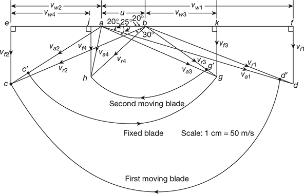
Figure 7.24 Velocity diagrams for a two stage impulse turbine
bg = ac′
bg = 3.6 cm, bg′ = 0.9 × 3.6 = 3.2 cm
∠abh = 30°, bh = bg′
Join ah
vw1 = af = 11.3 cm, vw2 = ea = 5.8 cm, vw3 = ak = 5.1 cm, vw4 = aj = 0.4 cm
Blade efficiency, ηb = 

Power developed = 
Example 7.3
In an impulse turbine, the mean diameter of the blades is 1.05 m and the speed is 3000 rpm. The nozzle angle is 18°, speed ratio is 0.42, and the friction factor is 0.84. The outlet blade angle is to be made 3° less than the inlet angle. The steam flow is 10 kg/s. Draw the velocity diagrams for the blades and calculate (a) the tangential thrust, (b) the axial thrust, (c) the resultant thrust, (d) the power developed, and (e) the blading efficiency.
Solution
Given that dm = 1.05 m, N = 3000 rpm, α1 = 18°, ρ = 0.42, K = 0.84, β2 = β1 − 3°, ṁ = 10 kg/s
Blade speed, u = ![]()
Draw the velocity diagrams as shown in Fig. 7.25.

Figure 7.25 Velocity diagrams for an impulse turbine

or β1 = 30.2°
β2 = 30.2 – 3 = 27.2°
vr2 = K vr1 = 0.84 × 241.28 = 202.67 m/s
vf 2 = vr2 sin β2 = 202.67 sin 27.2° = 92.64 m/s
vw1 = va1 cos α1 = 392.7 cos 18° = 373.48 m/s
vw2 = vr2 cos β2 − u = 202.67 cos 27.2° − 164.93 = 15.33 m/s
- Tangential thrust ṁ = (vw1 + vw2) = 10 (373.48 + 15.33) = 3888 N
- Axial thrust = ṁ (vf 1 − vf 2) = 10 (121.35 − 92.64) = 287.1 N
- Resultant thrust = [(3888)2 + (287.1)2]1/2 = 3898.6 N
- Power developed

- Blade efficiency, ηb =

Example 7.4
One stage of impulse turbine consists of a converging nozzle ring and moving blades. The nozzles are inclined at 22° to the blades whose tip angles are both 35°. If the velocity of steam at exit from nozzle is 660 m/s, find the blade speed so that the steam passes on without shock. Find the diagram efficiency neglecting losses if the blades are run at this speed.
[IES, 1992]
Solution
Given that α2 = 22°, β1 = β2 = 35°, va1 = 660 m/s
The velocity diagrams are shown in Fig. 7.26.
vf 1 = va1 sin 22° = vr1 sin 35°


Figure 7.26 Velocity diagrams for a single stage impulse turbine
vw1 = va1 cos α1 = 660 cos 22° = 611.94 m/s

or (431.05)2 = u2 + (660)2 − 2u × 660 cos 22°
or 185804 = u2 + 435600 − 1223.88 u
or u2 − 1223.88 u + 249796 = 0

For K = 1, vr2 = vr1 = 431.05 m/s
vw2 = vr2 cos β2 − u = 431.05 cos 35° − 258.85 = 94.24 m/s

Example 7.5
A single-stage steam turbine is supplied with steam at 5 bar, 200°C at the rate of 50 kg/min. It expands into a condenser at a pressure of 0.2 bar. The blade speed is 400 m/s. The nozzles are inclined at an angle of 20° to the plane of the wheel and the outlet blade angle is 30°. Neglecting friction losses, determine the power developed, blade efficiency, and stage efficiency.
[IES, 1994]
Solution
Given that p1 = 5 bar, t1 = 200oC, p2 = 0.2 bar, ṁ = 50 kg/min, u = 400 m/s, α1 = 20°, β2 = 30°, vr1 = vr2 as K = 1
At 5 bar, 200°C, h1 = 2855.4 kJ/kg, s1 = 7.0592 kJ/kg.K
At 0.2 bar, sf 2 = 0.8319 kJ/kg. K, sfg2 = 7.0766 kJ/kg.K
s2 = s1 = sf2 + x2sfg2
or 7.0592 = 0.8319 + 7.0766 x2
or x2 = 0.88
h2 = hf 2 + x2 hfg2 = 251.38 + 0.88 × 2358.3 = 2326.68 kJ/kg
Enthalpy drop, ∆h = h1 − h2 = 2855.4 − 2326.68 = 528.7 kJ/kg

or β1 = 31.84°

vr2 = vr1 = 655.6 m/s
vw2 = vr2 cos β2 − u = 665.6 cos 30° − 400 = 177 m/s
vw = vw1 + vw2 = 965.3 + 177.3 = 1143.6 m/s
Power developed, 
Blade efficiency, ηb =![]() = 0.8652 or 86.52%
= 0.8652 or 86.52%
Example 7.6
A simple impulse turbine has a mean blade speed of 200 m/s. The nozzles are inclined at 20° to the plane of rotation of the blades. The steam velocity from nozzle is 600 m/s. The turbine uses 3600 kg/h of steam. The absolute velocity at exit is along the axis of the turbine. Determine: (a) the inlet and exit angles of blades, (b) the power output of the turbine, (c) the diagram efficiency, and (d) the axial thrust (per kg steam per second). Assume inlet and outlet angles to be equal.
[IES, 1998]
Solution
Given that u = 200 m/s, α1 = 20°, va1 = 600 m/s, ṁ = 3600 kg/h, va2 = vf2
The velocity diagrams are shown in Fig 7.27.
- vf1 = va1 sin α1 = 600 sin 20° = 205.2 m/svw1 = va1 cos α1 = 600 cos 20° = 563.8 m/s

 Figure 7.27 Velocity diagrams for a simple impulse turbineor b1 = 29.42°β2 = β1 = 29.42°vw2 = 0
 - Power output of turbine =

- Diagram efficiency, =
 = 0.6264 or 62.64%
 - Axial thrust, Fa = ṁ(vf1 – vf2)vf 2 = u tan β2 = 200 tan 29.42° = 112.79 m/sFa = 1 × (205.2 − 112.79) = 92.41 N
Example 7.7
Steam at 2.94 bar absolute and dry saturated comes out of rotor of a reaction turbine having identical bladings. The velocity of steam entering into the turbine is 100 m/s. The mean blade height is 4 cm and the exit angle of the moving blade is 20°. The blade velocity is 4/3 times of axial flow velocity at the mean radius. If the steam flow rate is 2.5 kg/s, find (a) the rotor speed, (b) the power developed, (c) the diagram efficiency, (d) the percentage increase in relative velocity in the moving blades and (e) the enthalpy drop of steam in blade passage.
[IES, 1999]
Solution
The velocity triangles are shown in Fig. 7.28.
Given that p = 2.94 bar, h = 4 cm, va1 = 100 m/s, ṁ = 2.5 kg/s, α1 = β2 = 20°, β1 = α2, u = (4/3)vf
From velocity triangles, we have (Fig. 7.28)
vf = vf1 = vf2 = va1 sin α1 = 100 sin 20° = 34.2 m/s

Specific volume of steam at 2.94 bar (from steam tables), vs = 0.6173 m3/kg

Figure 7.28 Velocity diagrams for a reaction turbine having symmetrical blades
vs = πdhvf


- Power developed, P = ṁu (vw1 – vw2)

- Diagram efficiency


 Increase in relative velocity =
- Enthalpy drop:Fixed blades,
 Moving blades,
Example 7.8
In a multi-stage Parson’s reaction turbine, at one of the stages, the rotor diameter is 125 cm and the speed ratio 0.72. The speed of the rotor is 3000 rpm. Determine: (a) the blade inlet angle if the blade outlet angle is 22°, (b) diagram efficiency, and (c) percentage increase in diagram efficiency and rotor speed if the turbine is designed to run at the best theoretical speed.
[IES, 2000]
Solution
Given that d = 1.25m, N = 3000 rpm, ![]() = 0.72, α1 = β2 = 22°
= 0.72, α1 = β2 = 22°
 m/s
m/s  In Parson’s reaction turbine, (see Fig. 7.29) vr2 = va1, vr1 = va2 and a2 = b1vf1 = va1 sin α1 = 272.7 sin 22° = 102.15 m/svw1 = va1 cos α1 = 272.7 cos 22° = 252.84 m/s
 or β1 = 61° vr2 = 272.7 m/s
 Figure 7.29 Velocity diagrams for Parson’s reaction turbine
- vw2 = vr2 cos β2 – u = 272.7 cos 22° − 196.35 = 56.5 m/sDiagram efficiency,


- Power developed,
 kWAt best theoretical rotor speed, u = va1 cos α1 = 272.6 cos 22° = 252.84 m/sPercentage increase in rotor speed =
 = 0.2877 or 28.77%Diagram efficiency =
 Percentage increase in diagram efficiency =
Example 7.9
A De-Laval turbine has a mean blade velocity of 180 m/s. The nozzles are inclined at 17° to the tangent. The steam flow velocity through the nozzles is 550 m/s. For a mass flow of 3300 kg/hr and for axial exit conditions, find (a) the inlet and outlet angles of the blade system, (b) the power output, and (c) the diagram efficiency.
[IES, 2001]
Solution
Given that u = 180 m/s, va1 = 550m/s, ṁ = 3300 kg/h, α1 = 17°, α2 = 90°
The velocity diagrams are shown in Fig. 7.30.
- vf1 = va2 (see Fig. 7.30)vf1 = va1 sin α1 = 550 sin 17° = 160.8 m/stan β2 = vf1/u = 160.8/180 = 0.89336or β2 = 41.78° tan β1 = vf1/(va1 cos α1 − u)= 160.8/(550 cos 17° − 180) = 0.46478or β1 = 24.93°
 Figure 7.30 Velocity of diagrams for De-Laval turbine
 - Power output, P = ṁuvw1 = (3300/3600) × (180 × 550 cos 17°/103) = 85.785 kW
- Diagram efficiency =
 = 2 × 180 × 550 cos 17°/5502 = 0.626 or 62.6%
Example 7.10
A steam turbine is governed by throttling. The full load output of a steam turbine, measured at the coupling is 5 MW and the losses due to bearing friction, the governor and oil pump drive, etc., are 200 kW. The steam is supplied at a pressure of 20 bar and 300°C. The exhaust pressure of steam is 0.07 bar. The internal efficiency ratio at full load is 0.75. Calculate the coupling power of turbine when the steam flow through the turbine is 20% of that at full load. Assume that the external losses are the same as that at full load, exhaust pressure is the same, and the internal efficiency ratio is reduced to 70% at this load.
[IES, 2005]
Solution
The h–s (Mollier) diagram is shown in Fig 7.31.
At 20 bar, 300°C, h1 = 3020 kJ/kg
At 0.07 bar, h2 = 2100 kJ/kg
At full load:
Internal efficiency, ![]()
or ![]()
or h2‘ = 2330 kJ/kg
Δhi = 3020 − 2330 = 690 kJ/kg
Internal power developed, ![]()
or 5000 = ṁ × 690
or ṁ = 7.246 kg/s
Nozzle box pressure at part load ![]() = steam mass flow ratio × p1
= steam mass flow ratio × p1

Figure 7.31 Mollier diagram for a steam turbine
![]() = 0.2 × 20 = 4 bar
= 0.2 × 20 = 4 bar
![]() = 3020 − 2350 = 670 kJ/kg
= 3020 − 2350 = 670 kJ/kg
= 0.7 × 7.246 × 670 × 0.2 = 679.71 kW
Coupling power = 679.71 – 200 = 479.71 kW
Example 7.11
The turbine rotor has a mean blade ring diameter of 500 mm and the blade angles are equal. The nozzle angle is 20° and the steam leaves the nozzles with a velocity of 900 m/s. Assuming a blade friction factor of 0.85, determine the (a) the best blade angles, (b) the turbine speed in rpm, (c) the steam consumption rate in kg/h if the turbine generates 10 kW, and (d) the maximum blade efficiency.
[IES, 2006]
Solution
Given that α1 = 20°, dm = 0.5 m, va1 = 900 m/s, K = 0.85, β = β1 = β2 so that C = 1, P = 10 kW
The velocity diagrams are shown in Fig. 7.32.
For maximum blade efficiency, the speed ratio,


Figure 7.32 Velocity diagrams for an impulse turbine
vw = vw1 + vw2
= vr1 cos β1 + vr2 cos β2
= vr1 cos β (1 + KC) = 18.5 vr1 cos β
u = va1 cos α1 − vr1 cos β
vr1 cos β = 900 cos 20° − 422.86 = 422.86 m/s
vw = 1.85 × 422.86 = 782.25 m/s
Power developed by turbine, P = ![]()
Mass flow rate,![]() = 0.03023 kg/s or 108.83 kg/h
= 0.03023 kg/s or 108.83 kg/h
Maximum blade efficiency, ![]()

or vr1 = 523.03 m/s

or β = 36°

Leave a Reply