A shock wave involves an extremely rapid and abrupt change of state. In a normal shock, this change of state takes place across a plane normal to the direction of flow. Figure 6.17 shows a control surface that includes such a normal shock. Let subscripts x and y denote the conditions upstream and downstream of shock, respectively, and assuming steady-state, steady-flow with no heat and work transfer across the control surface, then the various relations are as follows:
First law: 
or hox = hoy

Figure 6.17 One-dimensional normal shock
Continuity equation:

Momentum equation:

Second law:

The energy and continuity equations can be combined to establish an equation that when plotted on the h − s diagram is called the Fanno line. Similarly, the momentum and continuity equations can be combined to establish an equation the plot of which on the h − s diagram is known as the Rayleigh line. Both these lines are shown on the h − s diagram in Fig. 6.18. The point of maximum entropy on each line, points ‘a’ and ‘b’, corresponds to M = 1. The lower part of each line corresponds to supersonic flow, whereas the upper part corresponds to subsonic flow.
The two points where all three equations are satisfied are points x and y, where x being in the supersonic region and y in the subsonic region. Since sy − sx ≥ 0, the normal shock can proceed only from x to y. This means that the velocity changes from supersonic (M > 1) before the shock to subsonic (M < 1) after the shock.
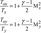
Assuming constant specific heats, the energy Eq. (6.26) gives,

That is, there is no change in stagnation temperature across a normal shock. Using Eq. (6.16), we have
and substituting into Eq. (6.30), we have
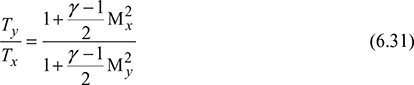

Figure 6.18 End states for a one-dimensional normal shock on an enthalpy–entropy diagram
ρxcx = ρycy
But 


Combining energy Eq. (6.31) and continuity Eq. (6.32) gives the equation of the Fanno line.

The momentum and continuity equations can be combined as follows to give the equation of the Rayleigh line.


Combining Eqs (6.33) and (6.34), we get

Table 6.3 gives the normal shock functions, which includes My as a function of Mx for γ = 1.4.
Table 6.3 One-dimensional normal shock functions for an ideal gas with constant specific heat and molecular weight and γ = 1.4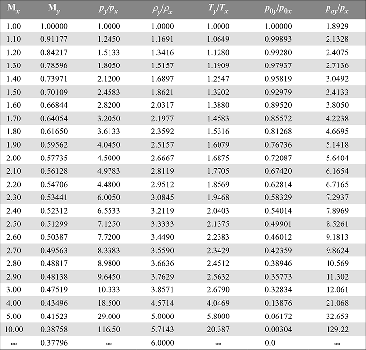
Example 6.9
For the convergent–divergent nozzle of Example 6.8 in which the diverging section acts as a supersonic nozzle (Fig. 6.19), a normal shock stands in the exit plane of the nozzle. Determine the static pressure and temperature and the stagnation pressure (a) just downstream of the normal shock and (b) at a point where M = 1.4.
Solution
- From Table 6.3, we have

 Figure 6.19 Convergent–divergent nozzlepy = 4.46 × 93.9 = 512.7 kPaTy = 1.854 × 183.2 = 339.7 Kpoy = 0.630 × 1000 = 630 kPa
 - From Table 6.1 at point x, as the flow is isentropic to point x,
 Therefore, px = 0.2724 × 1000 = 272.4 kPaTx = 0.6897 × 360 = 248.3 KThe properties at y can be determined from the normal shock functions (Table 6.3) as
 py = 2.4583 × 272.4 = 669.6 kPaTy = 1.320 × 248.3 = 327.8 Kpoy = 0.9298 × 1000 = 929.8 kPa
Tox = Toy = 360 K, as there is no change in stagnation temperature across a normal shock. From y to E, the diverging section acts as a diffuser.
Example 6.10
Steam at stagnation pressure of 800 kPa and a stagnation temperature of 350°C expands in a nozzle to 200 kPa. When the mass flow rate is 3 kg/s, determine the throat area and exit area for isentropic flow.
Solution
Critical pressure ratio at the throat, ![]() = 0.545
= 0.545
p* = 0.545 × 800 = 436 kPa
s* = s0 = 7.4089 kJ/kg. K
h0 = 3161.7 kJ/kg
T * = 268.7°C
h* = 3001.4 kJ/kg

At the nozzle exit,
pE = 200 kPa, sE = s0 = 7.4089 kJ/kg.K
TE = 178.5°C
hE = 2826.7 kJ/kg
vE = 1.0284 m3/kg

Example 6.11
5 kg/s of steam at 30 bar and 350°C is supplied to a group of 6 nozzles in a wheel diameter maintained at 4 bar. Calculate the following:
- The dimensions of the nozzles of rectangular cross-sectional flow area with aspect ratio of 2.5:1. The expansion may be considered metastable and friction is neglected.
- Degree of undercooling and supersaturation
- Loss in available heat drop due to irreversibility
- Increase in entropy
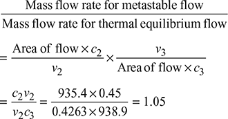
- Ratio of mass flow rate with metastable expansion to that if expansion is in thermal equilibrium.
Solution
The h-s diagram is shown in Fig. 6.20.
h1 = 3115.3 kJ/kg
v1 = 0.09053 m3/kg
s1 = 6.74257 kJ/kg.K
s3 = s1 = sf3 + x3sfg3
6.7427 = 1.7766 + x3 × 5.1193
x3 = 0.97
h3 = hf3 + x3hfg3
= 604.73 + 0.97 × 2133.8
= 2674.5 kJ/kg
v3 = vf3 + x3(vg3 − vf3) = 0.0010840.97 × (0.4625 − 0.001084)
= 0.45 m3/kg

Figure 6.20 Mollier diagram for superheated steam
- For supersaturated steam, n = 1.3
 Let breadth = bThen length, l = 2.5 bArea of 6 nozzles = 6 × 2.5b × b = 15b215b2 = 2.279 × 10⁻³b = 0.0123 m or 12.3 mml = 0.0308 m or 30.8 mm
  At 4 bar, ts = 143.65°CDegree of undercooling = 143.65 − 118.34 = 24.31°Cps corresponding to 118.3°C = 1.9 barDegree of super saturation =
  = 2.1
= 2.1- h1 = h3 = 3115.3 − 2674.5 = 440.8 kJ/kgLoss of available heat drop = (h1 − h3) − (h1 − h2)(Δh)loss = 440.8 − 437.5 = 3.3 kJ/kg
- Increase in entropy

Example 6.12
Dry saturated steam at 5 bar with negligible velocity expands isentropically in a convergent nozzle to 1 bar and dryness fraction 0.94. Determine the velocity of steam leaving the nozzle.
Solution
Given that p1 = 5 bar; p2 = 1 bar; x2 = 0.94
For p1 = 5 bar, enthalpy of dry saturated steam from steam tables,
h1 = hg1 = 2748.7 kJ/kg
and for p2 = 1 bar, we find that,
hf 2 = 417.44 kJ/kg, hfg2 = 2258.0 kJ/kg
∴ h2 = hf2 + x2 hfg2
= 417.44 + 0.94 × 2258.0 = 2539.96 kJ/kg
Enthalpy drop, Δh = h1 − h2
= 2748.75 − 2539.96 = 208.74 kJ/kg
Velocity of steam leaving the nozzle

Example 6.13
Dry saturated steam at a pressure of 15 bar enters in a nozzle and is discharged at a pressure of 1.5 bar. Find the final velocity of steam when initial velocity of steam is negligible. If 15% of the heat drop is lost in friction, then find the percentage reduction in the final velocity.
Solution
For p1 = 15 bar from steam tables,
h1 = 2792.1 kJ/kg
and for p2 = 1.5 bar,
h2 = 2693.5 kJ/kg
Enthalpy drop, Δh = h1 − h2
= 2792.19 − 2693.5 = 98.6 kJ/kg
Final velocity of steam,

Percentage reduction in the final enthalpy = 15% = 0.15
Nozzle coefficient or nozzle efficiency, ηn = 1 − 0.15 = 0.85
Final velocity of steam,

Percentage reduction in final velocity

Example 6.14
Steam approaches a nozzle with velocity of 250 m/s at a pressure of 3.5 bar and dryness fraction 0.95. If the isentropic expansion in the nozzle proceeds till the pressure at exit is 2 bar, then determine the change of enthalpy and dryness fraction of steam. Calculate also the exit velocity from the nozzle and the area of exit of nozzle for flow of 0.75 kg/s.
Solution
Given that c1 = 250 m/s, p1 = 3.5 bar, x1 = 0.95, p2 = 2 bar, ṁ = 0.75 kg/s
From Mollier diagram, as shown in Fig. 6.21,

Figure 6.21 Mollier diagram
h2 = 2534 kJ/kg
Δh = h1 − h2 = 2624 − 2534 = 90 kJ/kg
Dryness fraction, x2 = 0.92
From steam tables, vf2 = 0.001061 m3/kg, vg2 = 0.8857 m3/kg at p2 = 2 bar
Specific volume at exit
v2 = vf2 + x2 (vg2 − vf2) = 0.001061 + 0.92 × (0.8857 − 0.001061) = 0.8149 m3/kg
Now,  = h1 − h2

Steam mass flow rate (ṁ) is given by,

Example 6.15
Dry saturated steam at a pressure of 6 bar flows through a convergent–divergent nozzle at a rate of 4.5 kg/s and discharges at a pressure of 1.6 bar. The loss due to friction occurs only in the diverging portion of nozzle and its magnitude is 12% of total isentropic enthalpy drop. Assuming the isentropic index of expansion, n = 1.135, determine the cross-sectional area at throat and exit of nozzles.
Solution
Given that p1 = 6 bar, ṁ = 4.5 kg/s, p3 = 1.6 bar, n = 1.135, ηn = 1 − 0.12 = 0.88
From Mollier diagram shown in Fig. 6.22,
h1 = 2750 kJ/kg, h3 = 2520 kJ/kg
Refer to h − s diagram (Mollier chart) as shown in Fig. 6.22.
Let suffix 1, 2 and 3 denote entrance, throat, and exit.
We have 
p2 = 6 × 0.578 = 3.468 bar and
h2 = 2650 kJ/kg

For Section 1–2:
h1 − h2 = 2750 − 2650 = 100 kJ/kg
A2 = Area of throat
v2 = 0.964 m3/kg
From Mollier diagram, we have
vg2 = 0.5321 m3/kg corresponding to p2 = 3.468 bar
v2 = x2 vg2 = 0.964 × 0.5321 = 0.513 m3/kg

For Section 2–3:
(h1 − h3) isentropic = 230 kJ/kg
h1 − h3‘ = (h1 − h3) × ηn = 230 × 0.88 = 202.4 kJ/kg

From Mollier diagram,
x3‘ = 0.9365
vg3 = 1.0911 m3/kg corresponding to pressure of 1.6 bar.
v3 = x3‘ vg3 = 0.9365 × 1.0911 = 1.022 m3/kg


Example 6.16
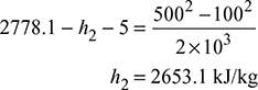
Dry saturated steam enters a nozzle at a pressure of 10 bar and velocity of 100 m/s. The discharge pressure is 5 bar and discharge velocity is 500 m/s. Heat loss from the nozzle is 5 kJ/kg. Determine the final dryness fraction of steam.
Solution
Given that p1 = 10 bar, c1 = 100 m/s, p2 = 5 bar, c2 = 500 m/s, q = −5 kJ/kg
Using steady flow energy equation

Since w = 0

At p1 = 10 bar, x1 = 1.0, h1 = 2778.1 kJ/kg
At 5 bar; hf2 = 640.21 kJ/kg, hfg2 = 2108.5 kJ/kg

Example 6.17
Steam enters a group of nozzles of a steam turbine at 12 bar and 220°C and leaves at 1.2 bar. The steam turbine develops 220 kW with a specific steam consumption of 13.5 kg/kWh. If the diameter of nozzles at throat is 7 mm, then calculate the number of nozzles.
Solution
Given that p1 = 12 bar, t1 = 220°C, p3 = 1.2 bar, power developed = 220 KW, m3 = 13.5 kg/kWh, and
d2 = 7 mm
Refer to Mollier diagram, as shown in Fig. 6.23.
The steam is initially superheated.
n = 1.3 and p2/p1 = 0.5457
p2 = 0.5457 p1 = 0.5457 × 12 = 6.548 bar
From Mollier diagram, we have
h1 = 2860 kJ/kg, h2 = 2750 kJ/kg, x2 = 0.992

vg2 = 0.29 m3/kg
Δh2 = h1 − h2 = 2860 − 2750 = 110 kJ/kg

A2 = Area of throat ![]()
Mass flow rate per nozzle

Total mass flow rate,

Example 6.18
Dry saturated steam at a pressure of 8 bar enters a convergent–divergent nozzle and leaves it at a pressure of 1.5 bar. If the flow is isentropic and the corresponding expansion index is 1.135, then find the ratio of cross-sectional area at exit and throat for maximum discharge.
Solution
Given that p1 = 8 bar, p3 = 1.5 bar, n = 1.135
Let A2 = Area of cross-section at throat
A3 = Area of cross-section at exit
m = mass of steam discharged per second
Refer to Mollier diagram as shown in Fig. 6.24.

For dry saturated steam, n = 1.135

From Mollier chart, h1 = 2775 kJ/kg
h2 = 2650 kJ/kg
h3 = 2465 kJ/kg
x2 = 0.965, x3 = 0.902
From steam tables, vg2 = 0.405 m3/kg, v’g2 = 1.159 m3/kg

Ratio of cross-sectional area at exit and throat = ![]()
Example 6.19
Steam at a pressure of 10 bar and dryness fraction of 0.98 is discharged through convergent–divergent nozzle to a back pressure of 0.1 bar. The mass flow rate is 10 kg/kWh. If the power developed is 220 kW, then determine the following:
- Pressure at throat
- Dimensions at exit of the nozzle if the throat is of rectangular cross-section of 5 mm × 10 mm.
The loss due to friction is 10% of the overall isentropic enthalpy drop in the divergent portion.
Solution
Refer to the Mollier diagram as shown in Fig. 6.25.
- The isentropic index of expansion for wet steam:n = 1.035 + 0.1x1n = 1.035 + 0.1 × 0.98 = 1.133
 Now p1 = 10 bar, p2 = 10 × 0.5778 = 5.778 bar
 - From Mollier diagram, we haveh1 = 2762 kJ/kg, h3 = 2075 kJ/kg, h2 = 2660 kJ/kgLoss in heat drop due to friction = 0.1 (h1 − h3) = 0.1 (2762 − 2075) = 68.7 kJ/kgh3‘ − h3 = 68.7h3‘ = h3 + 68.7 = 2075 + 68.7 = 2143.7 kJ/kg
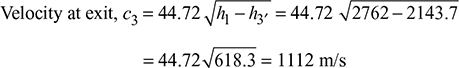
 Figure 6.25 Mollier diagramMass flow rate,
 Velocity at throat,
 Total area of throat,
  x2 = 0.953vg2 = 0.34 m3/kg at 5.778 bar (from steam tables)
 Throat area per nozzle = 5 × 10 × 10−6 = 0.5 × 10⁻⁴ m2Number of nozzles =
  = 7.97 = 8 (say)Exit area/nozzle =
  = 7.476 × 10⁻⁴ m2Keeping the same aspect ratio of 1:2 for rectangle and let x be the smaller side2x × x = 7.476 × 10−42x2 = 7.476 cm2
Therefore, exit rectangle is 19.33 mm × 38.66 mm.
Example 6.20
The dry saturated steam is expanded in a nozzle from pressure of 10 bar to pressure of 5 bar. If the expansion is supersaturated, then find (a) the degree of under cooling, and (b) the degree of supersaturation.
Given that p1 = 10 bar and p2 = 5 bar
From steam tables corresponding to p1 = 10 bar, saturation temperature of steam.
T1 = 179.91°C = 452.91 K
T2′ = Temperature at which supersaturation occurs

From steam tables corresponding to a pressure of 5 bar, we find saturation temperature
T2 = 151.86°C
∴ Degree of undercooling
= T2 − T2′ = 151.86 − 112.88 = 38.98°C
Example 6.21
Steam enters a nozzle in a dry saturated condition and expands from a pressure of 2 bar to 1 bar. It is observed that supersaturated flow is taking place and steam flow reverts to normal flow at 1 bar. What is the degree of undercooling and increase in entropy and loss in available heat drop due to irreversibility?
Solution
For supersaturated flow,

From steam tables at 2 bar,
T1 = (120.23 + 273) = 393.23 K
Hence, ![]() = 335 K
= 335 K
From steam tables corresponding to 1 bar, T2 (saturation temperature)
= 99.62°C = 99.62 + 273 = 372.62 K
Degree of undercooling
= T2 − T2‘ = 372.62 − 335 = 37.62 K
Refer to the Mollier diagram as shown in Fig. 6.26.
Corresponding to 335 K, saturation pressure from steam tables = 0.22 bar.
∴ p2‘ = 0.22 bar

Degree of supersaturation = ![]() = 4.545
= 4.545
For supersaturated flow, the formula for superheated steam is used.
Thus, 
where n = 1.3
v1 = 0.8857 m3/kg from steam tables

Isentropic heat drop = (h1 − h2) = 117.5 kJ/kg (from Mollier diagram)
Therefore, loss in availability = 117.5 − 113.5 = 4 kJ/kg
Increase in entropy = ![]() = 0.01073 kJ/kg.K
= 0.01073 kJ/kg.K
Example 6.22
Find the percentage increase in discharge from a convergent–divergent nozzle expanding steam from 8.75 bar dry to 2 bar, when (a) the expansion is taking place under thermal equilibrium and (b) the steam is in metastable state during part of its expansion.
Take area of nozzle as 2500 mm2.
Solution
Given that p1 = 8.75 bar, p2 = 2 bar, A2 = 2500 mm2 = 2500 × 10–6 m2
Refer to the Mollier diagram shown in Fig. 6.27.
- Mass of steam discharged when expansion is under thermal equilibrium.Let ṁ1 = Mass of steam dischargedFrom Mollier diagram, h1 = 2770 kJ/kg, h2 = 2515 kJ/kg, and x2 = 0.91From steam tables,
 Figure 6.27 Mollier diagramvg2 = 0.885 m3/kgΔh2 = h1 − h2 = 2770 − 2515 = 255 kJ/kgVelocity of steam at exit,
- Mass of steam discharged when it is in metastable state.Let ṁ2 = mass of steam dischargedVolume of steam at inlet,
 Volume of steam at exit,
 Furthermore,
 Heat drop from inlet to exit Δh2 = h1 − h2 = 2770 − 2530 = 240 kJ/kgVelocity of steam at exit,
 ∴ Percentage increase in discharge
Example 6.23
Steam expands through a nozzle from 5 bar and dry saturated to a back pressure of 0.2 bar. Mass flow is 2 kg/s. Calculate the exit and the throat areas under the following conditions:
- Isentropic expansion with negligible velocity
- Isentropic expansion with initial velocity of 100 m/s
- Friction loss at pressure amounts to 10% of the total heat drop up to that pressure and initial velocity negligible
Solution
- Pressure at throat is given by p2 = 0.5774 × p1 = 0.5774 × 5 = 2.887 barDrop a vertical from point 1 to cut pressure for 2.887 bar at point 2 and the pressure line for 0.2 bar, i.e., the back pressure at point 3. Then from the Mollier diagram (Fig. 6.28), the following values are obtained:At point 1, h1 = 2745 kJ/kgAt point 2, p2 = 2.887 bar, h2 = 2645 kJ/kg, and v2 = 0.63 m3/kgAt point 3, p3 = 0.2 bar, h3 = 2248 kJ/kg, and v3 = 6.6 m3/kg
 Figure 6.28 Mollier diagramHence, the area at throat for a mass flow of 2 kg/s is given by,
 Similarly, area at exit for a mass flow of 2 kg/s is given by,
- Refer Fig. 6.29.
 Hence, h0 = 5.0 + h1 = 5 + 2745 = 2750 kJ/kgCorresponding to h0 = 2750 kJ/kgp0 = 5.1 bar as shown on the chartThus, the problem is resolved to the condition of p0 = 5.1 bar and h0 = 2750 kJ and velocity of zero at entry to the nozzle.Therefore, pressure at throat is given by,
 And at p2 = 2.945 bar h2 = 2653 kJ/kg, v2 = 0.61 m3/kg, from the Mollier chart p3 = 0.2 bar h3 = 2248 kJ/kg, v3 = 6.6 m3/kg, from the Mollier chart
 Figure 6.29 Mollier diagramArea at throat is given by,
 Similarly, area at the exit from the nozzle is given by,
 The nozzle efficiency ηn = 0.9 and n = 1.135 for dry saturated steam.Therefore, m =
  = 1.119The critical pressure ratio is given by,
 And the discharge per unit area is given by,
 Area at throat, A2 =
 Using the same formula and putting the value of rp =
  we get
 Therefore, area at exit is given by,
 The area at the exit may also be found with the help of Mollier diagram (Fig. 6.30). Isentropic enthalpy drop as found in part (a) = 497 kJ/kg.Therefore, the actual heat drop = 0.9 × (2745 − 2248) kJ/kg= 497 + 0.9 = 447.3 kJ/kg
 Figure 6.30 Mollier diagrami.e., h1 − h’3 = 447.8 kJ/kgand v3′ = 6.7 m3/kgTherefore, area at exit is given by,
Example 6.24
A convergent–divergent nozzle is required to discharge 2 kg of steam per second. The nozzle is supplied with steam at 7 bar and 180°C and discharge takes place against a back pressure of 1 bar. The expansion up to throat is isentropic and the frictional resistance between the throat and the exit is equivalent to 63 kJ/kg of steam. Taking approach velocity of 75 m/s and throat pressure of 4 bar, estimate: (a) suitable areas for the throat and exit and (b) overall efficiency of the nozzle based on the enthalpy drop between the actual inlet pressure and temperature and the exit pressure.
Solution
Given that ṁ= 2 kg/s; p1 = 7 bar, T1 = 180°C, p3 = 1 bar, frictional resistance = 63 kJ/kg of steam, c1 = 75 m/s, p2 = 4 bar
- Suitable areas for the throat and exitLet A2 = area at the throatA3 = area at the exitThe expansion of steam through the nozzle on the Mollier diagram is shown in Fig. 6.31. From the Mollier diagram, we find that
 Figure 6.31 Mollier diagramh1 = 2810 kJ/kg, h2 = 2680 kJ/kg, h3 = 2470 kJ/kg, x2 = 0.97, and x3 = 0.934From steam tables, we also find that the specific volume of steam at throat corresponding to 4 bar,vf2 = 0.001084 m3/kg, vg2 = 0.4625 m3/kgv2 = vf2 + x2(vg2 − vf2) = 0.001084 + 0.97(0.4625 − 0.001084) = 0.449 m3/kgand specific volume of steam corresponding to 1 bar,vf3 = 0.001043 m3/kg, vg3 = 1.694 m3/kgv3 = vf3 + x3(vg3 − vf3) = 0.001043 + 0.934(1.694 − 0.001043) =1.582 m3/kgHeat drop between entrance and throat,Δh2 = h1 − h2 = 2810 − 2680 = 130 kJ/kg∴ Velocity of steam at throat,
 Since there is a frictional resistance of 63 kJ/kg of steam between the throat and the exit,h3 − h’3 = 63 or h3 = h’3 + 63 = 2470 + 63 = 2533 kJ/kgand heat drop between entrance and exit,Δh3 = h1 − h3 = 2810 − 2533 = 277 kJ/kg∴ Velocity of steam at exit,
- Overall efficiency of the nozzleOverall efficiency of the nozzle
Example 6.25
Air is expanded reversibly and adiabatically in a nozzle from 13 bar and 150°C to a pressure of 6 bar. The inlet velocity of the nozzle is very small and the process occurs under steady-state flow conditions. Calculate the exit velocity of the nozzle.
Solution
Given that p1 = 13 bar, T1 = 273 + 180 = 423 K, p2 = 6 bar, and c1 = 0
SFEE for unit mass flow rate is:


Figure 6.32 Flow through steam nozzle
Since the air expands reversibly and adiabatically from state 1 to 2, as shown in Fig. 6.32, we have q = 0, w = 0, and z1 = z2
Exit velocity of the nozzle,

Example 6.26
A steam nozzle receives steam at 40 bar and 400°C at an initial velocity of 40 m/s. The final pressure of steam is 10 bar. The mass flow rate of steam is 2 kg/s. The nozzle efficiency is 90%. The cross-section of the nozzle is circular. The angle of divergence is 6°. Calculate the throat and exit diameters and the length of the divergent portion. Show the representation of process on h − s diagram and sketch the nozzle and label the dimensions calculated.
[IES, 2005]

Figure 6.33 Flow through convergent-divergent steam nozzle
Solution
The convergent–divergent nozzle is shown in Fig. 6.33 and h − s diagram in Fig. 6.34.
From steam tables and Mollier diagram, we have
h1 =3213.5 kJ/kg for p1 = 40 bar and t = 400°C
p2 = 0.5457, p1 = 0.5457 × 40 = 21.828 bar, for superheated steam
h2 = 3025 kJ/kg, vs2 = 0.125 m3/kg
c2 = [2(h1 − h2) × 103 + ![]() ]0.5
]0.5
= [2(3213.5 − 3025) × 103 + 402]0.5 = 615.3 m/s


Figure 6.34 h − s diagram
In Fig. 6.34,

Leave a Reply