The isentropic expansion of superheated steam from supply pressure p1 to back pressure pb can be represented on the Mollier diagram by line AE, as shown in Fig. 6.5. During expansion, change of phase must start at point B where the pressure line p2 meets the saturation line. However, in nozzles, under certain conditions, this phenomenon of condensation does not occur at point B as the time available is very short due to very high velocity of steam (nearly sonic) through the nozzle. The equilibrium between the vapour phase and liquid is, therefore, delayed and the vapour continues to expand in dry state even beyond point B upon point B1. The pressure at B1 can be found by extending the superheated constant pressure line p3 up to B1. The steam during the expansion BB1 remains dry and condensation is suppressed.
The vapours between pressure p2 and p3 are said to be supersaturated or supercooled and such a flow in nozzles is called supersaturated or metastable flow of steam. A limit to the supersaturated state was observed by Wilson and the line drawn on the Mollier chart through the observed points is known as Wilson line. For all practical purposes, this line has become the saturation line.
The flow is also called supercooled flow because at any pressure between p2 and p3, the temperature of the vapour is always lower than the saturation temperature corresponding to that pressure. The difference in this temperature is called the degree of undercooling.
When the expansion reaches at point B, on the Wilson line, the condensation occurs at constant enthalpy, and the pressure remaining constant, as shown by horizontal line BC. Further isentropic expansion to the exit pressure is represented by CD. The ratio of saturation pressures corresponding to the temperatures at B and B1 is called the degree of supersaturation.

Figure 6.5 Super-saturated flow of steam in a nozzle
Velocity of steam at the end of expansion,

Specific volume, v2 = v1 
Temperature, T2 = T1 
and A2 = ![]()
The superheated expansion law, pv1.3 = constant, is followed in the supersaturated flow.
Example 6.1
Steam expands from 2.5 bar to 1 bar in a nozzle. The initial velocity of steam is 80 m/s and initial temperature is 200°C. Taking nozzle efficiency as 96%, find the exit velocity.
Solution
Given that p1 = 2.5 bar, p2 = 1 bar, c1 = 80 m/s, t1 = 200°C, ηn = 0.96
The h – s diagram is shown in Fig. 6.6.
From steam tables for superheated steam, we have
h1 = 2868 kJ/kg at p1 = 2.5 bar and 200°C
s1 = 7.3593 kJ/kg.K
At p2 = 1 bar, sf 2 = 1.3025 kJ/kg.K and sfg2 = 6.0568 kJ/kg.K
Since s1 > sfg2, steam is superheated. At 1 bar and s1 = 7.3593 kJ/kg.K, the enthalpy for superheated steam by interpolation is:


Figure 6.6 Steam flow through a nozzle
Enthalpy drop = h1 – h2 = 2868 – 2691.95 = 176.05 kJ/kg
Actual enthalpy drop, (Δh)actual = ηn (h1 − h2) = 0.96 × 176.05 = 169.0 kJ/kg

Example 6.2
Superheated steam enters a convergent–divergent nozzle at 20 bar and 300°C. The exit pressure is 4.5 bar. Assuming frictionless flow up to the throat (pv1.3 = const.) and a nozzle efficiency of 90%, determine (a) the flow rate for a throat area of 30 cm2 and (b) exit area.
Solution
Given that p1 = 20 bar, t1 = 300°C, p3 = 4.5 bar, ηn = 0.9, A2 = 30 cm2
Critical pressure ratio, 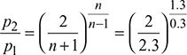 = 0.5457
Throat pressure, p2 = 20 × 0.5457 = 10.91 bar
From Mollier diagram (Fig. 6.7), we get
h1 = 3025 kJ/kg, h2 = 2880 kJ/kg, v2 = 0.2 m3/kg, h3 = 2700 kJ/kg, vs3′ = 0.4 m3/kg, and x3′ = 0.995


Figure 6.7 Superheated steam flow through a nozzle
v3 = x3′ vs3′ = 0.995 × 0.4 = 0.398 m3/kg

Example 6.3
Dry saturated steam at 3 bar is expanded through a convergent nozzle to 1.5 bar. The exit area is 2.5 cm2. Calculate the exit velocity and mass flow rate, assuming (a) isentropic expansion, (b) supersaturated flow, and (c) degree of under-cooling at exit.
Solution
- At p1 = 3 bar s1 = 6.992 kJ/kg.K, h1 = 2724.3 kJ/kg, v1 = 0.6058 m3/kgAt p2 = 1.5 bar s1 = s2 = sf 2 + x2 sfg26.9918 = 1.4335 + x2 × 5.7897 x2 = 0.96 h2 = hf2 + x2hfg2 = 467.08 + 0.96 × 2226.5 = 2604.52 kJ/kg v2 = vf2 + x2 (vg2 − vf2) = 0.001053 + 0.96 × (1.159 − 0.001053) = 1.113 m3/kg

- For supersaturated flow, pv1.3 = const.

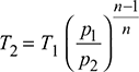
 Saturation temperature at 1.5 bar = 111.37°CDegree of under cooling at exit = 111.37 − 73.45 = 37.92°C.
Example 6.4
Steam at a pressure of 10 bar, 0.96 dry is expanded through a convergent–divergent nozzle and leaves the nozzle at 0.3 bar.
- Calculate the velocity of steam at throat for maximum discharge. Take n = 1.134.
- Calculate the exit area and steam discharge if the throat area is 1.5 cm2. Assume isentropic flow and ignore friction losses.
Solution
The nozzle is shown in Fig. 6.8.
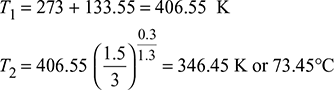
- v1 = vf1 + x1 (vg1 − vf1) = 0.001127 + 0.96 × (0.19444 − 0.001127) = 0.1867 m3/kgFor maximum discharge,
 Velocity of steam at throat, c2 =
 Figure 6.8 Convergent–divergent nozzle
 - For isentropic flow,s1 = sf1 + x1sfg1 = 2.1386 + 0.96 × 4.4478 = 6.4085 kJ/kgs1 = s2sf1 + x1sfg1 = sf2 + x2sfg2
 At p2 = 5.774 bar
 6.4085 = 1.9157 + x2 × 4.857 x2 = 0.925 h2 = hf2 + x2hfg2 = 663.92 + 0.925 × 2091.14 = 2598.22 kJ/kg h1 = hf1 + x1hfg1 = 762.79 + 0.96 × 2015.3 = 2697.5 kJ/kg
 At p3 = 0.8 bar, sf3 = 1.233 kJ/kg.K, sfg3 = 6.202 kJ/kg.K s2 = s3 sf2 + x2 sfg2 = sf3 + x3 sfg3 1.9157 + 0.925 × 4.857 = 1.233 + x3 × 6.202 x3 = 0.833 h3 = hf3 + x3hfg3 = 391.7 + 0.833 × 2274.1 = 2286 kJ/kg
Example 6.5
A convergent–divergent nozzle is supplied with steam at 10 bar and 250°C. The divergent portion of the nozzle is 4 cm long and throat diameter is 6 mm. Find the semi-cone angle of the divergent section so that steam may leave the nozzle at 1.2 bar. The frictional loss in the nozzle is 10 percent of the total enthalpy drop. Assume that the frictional loss occurs only in the divergent part of the nozzle.
Solution
Assuming maximum discharge, the throat pressure,

For superheated steam, n = 1.3

The nozzle and the h − s (Mollier) diagram is shown in Fig. 6.9. Locate point ‘1’ on the Mollier diagram corresponding to p1 = 10 bar and 250°C. Draw a vertical line from point ‘1’ to cut the p2 line at point ‘2’ and p3 line at point 3.
Length (1 − 4) = 0.9 × Length (1 − 3)
Draw horizontal line 4 − 3′ to cut p3 line at point 3′. Point 3′ gives the exit condition of steam.
From the Mollier diagram, we have
p1 = 10 bar: h1 = 2940 kJ/kg
p2 = 5.457 bar: h2 = 2830 kJ/kg, v2 = 0.4 m3/kg
p3 = 1.2 bar: h3 = 2530 kJ/kg, x3′ = 0.955, vs3′ = 1.5 m3/kg
h1 − h3 = 2940−2530 = 410 kJ/kg
h4 − h3 = 0.1 × 410 = 41 kJ/kg
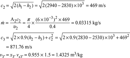

Figure 6.9 Superheated steam flow through a convergent–divergent nozzle

Example 6.6
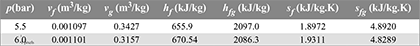
Dry saturated steam at pressure of 5 bar flows through a convergent–divergent nozzle at the rate of 4 kg/s and discharges at a pressure of 1.5 bar. The loss due to friction occurs only in the diverging portion of the nozzle and its magnitude is 15% of the total isentropic enthalpy drop. Assume the isentropic index of expansion n = 1.135. Determine the area of cross-section at the throat and exit of the nozzle.
Solution
Refer to Fig. 6.10.
For maximum discharge,

From steam table, we get
h1 = 2748.7 kJ/kg, s1 = 6.8212 kJ/kg.K
Now, s1 = s3 = sf3 + x3sfg3
6.8212 = 1.4335 + x3 × 5.7997
x3 = 0.93
h3 = hf 3 + x3hfg3 = 467.08 + 0.93 × 2226.5 = 2537.7 kJ/kg
(h1 − h3)isen = 2748.7 − 2537.7 = 211 kJ/kg
h1 − h3′ = h1 − h4 = 0.85 × 211 = 179.35 kJ/kg
From Mollier diagram (Fig. 6.10), x2 = 0.965, x3′ = 0.945, h2 = 2662 kJ/kg
vs2 = 0.7 m3/kg, vs3′ = 1.1 m3/kg, h3′ = 2585 kJ/kg
v2 = x2vs2 = 0.965 × 0.7 = 0.676 m3/kg
v3′ = x3′vs3′ = 0.945 × 1.1 = 1.04 m3/kg


Figure 6.10 Dry saturated steam flow through a convergent–divergent nozzle
Leave a Reply