Rankine cycle is the theoretical cycle on which the steam engine works. The Rankine cycle is shown in Fig. 5.4.
The p–v, T–s and h–s diagram for the Ranking cycle are shown in Fig. 5.5.
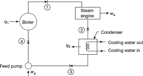
Figure 5.4 Rankine cycle

Figure 5.5 Rankine cycle in various ordinates: (a) p-v diagram, (b) T-s diagram, (c) h-s diagram
The various processes of Rankine cycle are:
Process 1-2: Reversible adiabatic expansion in the engine.
Process 2-3: Reversible constant pressure heat transfer in the condenser.
Process 3-4: Reversible adiabatic pumping process in the feed pump.
Process 4-1: Reversible constant pressure heat transfer in the boiler.
The steam on entry into the engine can be wet, dry saturated or superheated. Considering 1 kg of steam and applying steady flow energy equation to boiler, engine, condenser and pump, we have:
Boiler:
hf 4 + q1 = h1
q1 = h1 − hf 4
Engine:
h1 = we + h2
Condenser:
h2 = q2 + hf 3
q2 = h2 − hf 3
Feed pump:
hf 3 + wp = hf 4
Pump work, wp = hf 4 − hf 3
Net work, wnet = we − wp
Rankine cycle efficiency, 

The feed pump handles liquid water which is incompressible. This implies that with the increase in pressure its density or specific volume undergoes a small change. For reversible adiabatic compression, we have
T ds = ah − v dp
ds = 0
dh = v dp
or Δh = v Δp [∵ Δv = 0]
or hf4 − hf3 = v3 (p1 − p2) × 105 J/kg
Now. hf4 − hf3 = wp << we, and can be neglected

Leave a Reply