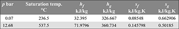
In a binary-vapour cycle, the steam cycle operates between 30 bar, 0.07 bar and uses a superheated temperature of 350°C. The mercury cycle works between 12.68 bar and 0.07 bar. The mercury vapour entering the turbine is in a dry saturated condition. Calculate the efficiency of the combined cycle assuming expansion in both cycles to be isentropic. Data for mercury is given below:
Solution
The binary vapour cycle is shown in Fig. 4.26.
Mercury cycle: sa = sb = sfb + xb (sgb − sfb)
0.50185 = 0.08548 + xb (0.662906 − 0.08548)
or xb = 0.721
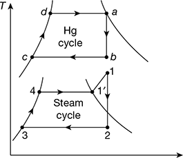
Figure 4.26 Binary vapour cycle neglecting pump work
= 32.395 + 0.721 (326.667 − 32.395) = 244.565 kJ/kg of Hg
Isentropic work done, wm = ha − hb = 360.734 − 244.565 = 116.169 kJ/kg Hg
Heat rejected, qrm = hb − hfb = 244.565 − 32.395 = 212.17 kJ/kg Hg
Heat supplied, qsm = ha − hfb = 360.734 − 32.395 = 328.339 kJ/kg Hg
Steam cycle: h1 = 3115.3 kJ/kg, s1 = 6.743 kJ/kg.K, h′1 = 2804.2 kJ/kg
sf2 = 0.5589 kJ/kg.K, sfg2 = 7.7179 kJ/kg.K, hf3 = 163.40 kJ/kg
s1 = s2 = sf2 + x2 sfg2
or 6.743 = 0.5589 + x2 × 7.7179
or x2 = 0.80127
h2 = hf2 + x2 hfg2 = 163.40 + 0.80127 × 2409.1 = 2093.733 kJ/kg
Work done, ws = h1 − h2 = 3115.3 − 2093.733 = 1021.567 kJ/kg
Heat supplied, qss = h1 = h1′ = 3115.3 − 2804.2 = 311.1 kJ/kg
Heat rejected by Hg/kg of steam = Heat received by water/kg steam
mm (hb − hfb) = 1 (h1′ − hf3)
or ![]()
Total work done per kg of steam,
w1 = ws + mm wm = 1021.567 + 12.447 × 116.161 = 2467.379 kJ/kg steam
Heat supplied in the cycle,
qs = mm qsm + qss = 12.447 × 328.339 + 311.1 = 4397.936 kJ/kg steam
Cycle efficiency = ![]()
Example 4.12
In a single-heater regenerative cycle, the steam enters the turbine at 32 bar, 350°C and the exhaust pressure is 0.12 bar. The feed water heater is a direct contact type which operates at 4.5 bar. Find (a) the efficiency and the steam rate of the cycle and (b) the increase in efficiency and steam rate as compared to Rankine cycle. Neglect pump work.
Solution
From steam tables, h1 = 3113.2 kJ/kg, s1 = 6.712 kJ/kg.K = s2 = s3
sg at 4.5 bar = 6.875 kJ/kg.K
The schematic diagram is shown in Fig. 4.27(a). The processes on the T-s and h-s diagrams are shown in Figs. 4.27(b) and (c) respectively. Since s2 < sg, state point 2 lies in the wet region.
sf2 = 1.821 kJ/kg.K, sfg2 = 5.036 kJ/kg.K
s1 = s2 = sf2 + x2 sfg2
or 6.712 = 1.821 + x2 × 5.036
or x2 = 0.9712
h2 = hf 2 + x2 hfg2 = 623.3 + 0.9712 × 2120.6 = 2682.83 kJ/kg
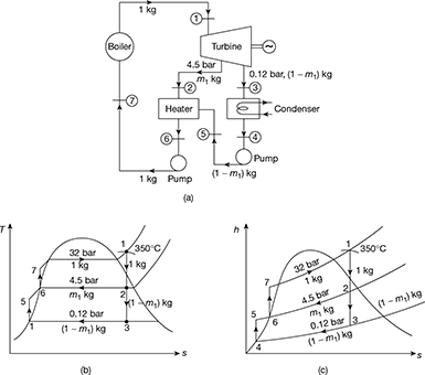
Figure 4.27 Single stage regenerative cycle: (a) Flow schematic diagram, (b) T-s diagram, (c) h-s diagram
sf3 = 0.6963 kJ/kg.K sfg3 = 7.3900 kJ/kg.K
s1 = s3 = sf3 + x3 sfg3
or 6.712 = 0.6963 + x2 × 7.3900
or x3 = 0.814
h3 = hf3 + x3 hfg3 = 206.92 ÷ 0.814 × 2384.1 = 2147.58 kJ/kg
Since wp = 0
∴ h4 = hf3 = 206.92 kJ/kg = h5
h6 = hf2 = 623.3 kJ/kg = h7
Energy balance for heater gives,
m1 (h2 − h6) = (1 − m1) (h6 − h5)
or m1 (2682.83 − 623.3) = (1 − m1) (623.3 − 206.92)
or 2059.53 m1 = (1 − m1) × 416.38
or m1 = 0.168 kg
wt = (h1 − h2) + (1 − m1) (h2 − h3)
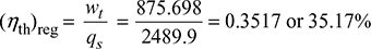
= (3113.2 − 2682.83) + (1 − 0.168) (2628.83 − 2147.58) = 875.698 kJ/kg
qs = h1 − h6 = 3113.2 − 623.3 = 2489.9 kJ/kg
Steam rate = ![]()
Without regeneration, wt = h1 − h3 = 3113.2 − 2147.58 = 965.62 kJ/kg
Increase in cycle efficiency due to regeneration = 35.17 − 33.22 = 1.95%
Steam rate = ![]()
Increase in steam rate due to regeneration = 4.11 − 3.728 = 0.382 kg/kWh
Example 4.13
A steam power plant working on Rankine cycle is supplied with dry saturated steam at a pressure of 12 bar and exhausts into the condenser at 0.1 bar. Neglecting the pump work, calculate the cycle efficiency.
Solution
Corresponding to p = 12 bar, from steam tables we find that (see Fig. 4.3)
hf1 = 798.4 kJ/kg; hg1 = 1984.3 kJ/kg
s1 = sg1 = 6.519 kJ/kg°K
Corresponding to 0.1 bar, we find that
hf2 = 191.8 kJ/kg; hfg2 = 2393 kJ/kg
sf2 = 0.649 kJ/kg K; sfg2 = 7.502 kJ/kg·K
Process 1–2 is an isentropic expansion
s1 = s2
s1 = sg1 = 6.519 kJ/kg K
s2 = sf 2 + x2 sfg2
s2 = 0.649 + x2 × 7.502
6.519 = 0.649 + 7.502 x2
x3 = 0.783
h2 = hf2 + hfg2
=191.81 + 0.783 × 2392.8 = 2065.5 kJ/kg
h1 = hg2 = 2782.7 kJ/kg
Example 4.14
Dry saturated steam at 10 bar is supplied to a prime mover working on Rankine cycle and the exhaust takes place at 0.2 bar. Determine the cycle efficiency, efficiency ratio, and specific steam consumption of the prime mover, if the indicated thermal efficiency is 20%. Determine the percentage change in the cycle efficiency if the steam is initially 90% dry.
Solution
The h-s diagram is shown in Fig. 4.28.
From Mollier diagram (Fig. 4.28), we have
h1 = 2775 kJ/kg, h2 = 2150 kJ/kg
From steam tables,
hf2 = 251.5 kJ/kg corresponding to 0.2 bar
Thermal efficiency ![]()
Efficiency ratio = ![]()
Specific steam consumption = ![]()
Percentage change in cycle efficiency if steam is initially 90% dry
From Mollier diagram, h1 = 2580 kJ/kg, h2 = 2030 kJ/kg (see Fig. 4.29)
Thermal efficiency ![]()
∴ Percentage change in Rankine efficiency =![]()
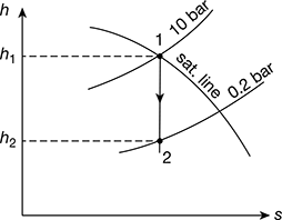
Figure 4.28 Mollier diagram for dry saturated steam
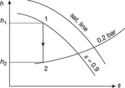
Figure 4.29 Mollier diagram for wet steam
Example 4.15
The steam consumption of steam engine is 20 tonnes per shift of 8 hours when developing 220 kW. Dry and saturated steam enters the engine at 10 bar pressure and leaves at 0.1 bar pressure. Estimate the cycle efficiency and thermal efficiency of engine.
Solution
Given that ms = 20/8 tonne/h = 2.5 tonne/h = 2500 kg/h, P = 220 kW
The h-s diagrams is shown in Fig. 4.30.
From steam tables corresponding to 10 bar
h1 = hg1 = 2778.1 kJ/kg; s1 = sg1 = 6.5864 kJ/kg.K
and corresponding to 0.1 bar, we find that
hf2 = 191.81 kJ/kg; hfg2 = 2392.8 kJ/kg;
sf2 = 0.6492 kJ/kg.K; sg2 = 7.5010 kJ/kg.K
Since 1−2 is an isentropic process
s1 = s3
or 6.5864 = 0.6492 + x2 × 7.5010
or x2 = 0.791
∴ h3 = hf2 + x2 hfg2 = 191.81 + 0.791 × 2392.8 = 2084.5 kJ/kg
Cycle Efficiency (ηR) = ![]()
Thermal efficiency of engine;


Figure 4.30 Mollier diagram for dry saturated steam
Example 4.16
Steam at 50 bar, 400°C expands in a Rankine engine to 0.34 bar. For 150 kg/s of steam; determine (a) the power developed, (b) the thermal efficiency neglecting the pump work, and (c) the specific steam consumption.
Solution
The h-s diagrams is shown in Fig. 4.31.
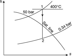
Figure 4.31 Mollier diagram for superheated steam
- Power developed = m(h1 − h2)From Mollier diagram (Fig. 4.31), we haveh1 = 3198.3 kJ/kg, h2 = 2257.75 kJ/kghf2 = 301.5 kJ/kg (from steam tables)Power developed = 150 [3198.3 − 2257.75] = 141082 kW
- Thermal efficiency
- Specific steam consumption =
Example 4.17
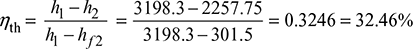
A steam engine is supplied with dry saturated steam at 15 bar. The pressure at release is 3 bar and the back pressure is 1 bar. Determine the efficiency of modified Rankine cycle.
Solution
Consider the Mollier diagram, as shown in Fig. 4.32.
From the Mollier diagram, we have
h1 = 2790 kJ/kg, h2 = 2510 kJ/kg, x2 = 0.9
From steam tables, corresponding to 3 bar, we have
vf2 =0.001073 m3/kg, vg2 = 0.6058 m3/kg
∴ Volume of steam at point 3,
v2 = vf2 + x2 (vg2 − vf2) = 0.001073 + 0.9 × (0.60585 − 0.001073) = 0.545 m3/kg
Figure 4.32 Mollier diagram for dry saturated steam
From steam tables corresponding to pressure of 1 bar, we find that sensible heat of water,
hf4 = 417.44 kJ/kg
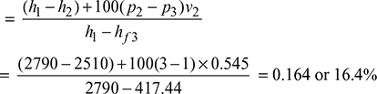
ηMR = Thermal efficiency of modified Rankine cycle
Example 4.18
Steam at a pressure of 15 bar and 250°C is first expanded through a turbine to a pressure of 4 bar. It is then reheated at constant pressure to the initial temperature of 250°C and is finally expanded to 0.1 bar. Estimate the work done per kg of steam flowing through the turbine and the amount of heat supplied during the process of reheat.
Find the work output when there is direct expansion from 15 bar to 0.1 bar without any reheat. Assume all expansion processes to be isentropic.
Solution
Given that p1 = 15 bar; T1 = 250°C; p2 = 4 bar; T2 = 250°C; p3 = 0.1 bar
The reheating of steam is represented on the Mollier chart as shown in Fig. 4.33. From the chart, we find that,
h1 = 2930 kJ/kg; h2 = 2660 kJ/kg; h3 = 2965 kJ/kg; h4 = 2345 kJ/kg; and h5 = 2130 kJ/kg
From steam tables, corresponding to a pressure of 0.1 bar, we find that sensible heat of water at D,
hf4 = hf5 = 191.81 kJ/kg
Workdone per kg of steam:
We know that workdone per kg of steam,
w = (h1 − h2) + (h3 − h4)
= (2930 −2660) + (2965 − 2345) = 890 kJ/kg
Heat supplied during the process of reheat:
We know that the heat supplied during the process of reheat,
h = Heat supplied between 2 and 3
= (h3 − h2) − (hf4) = (2965 − 2660) − 191.81 = 113.2 kJ/kg
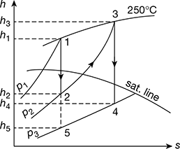
Figure 4.33 Mollier diagram for superheated steam with reheating
Work output when the expansion is direct:
The direct expansion from 15 bar to 0.1 bar is shown by the line AE in Fig. 4.33. We know that work output
= Total heat drop = h1 − h5 = 2930 − 2130 = 800 kJ/kg
Example 4.19
In a thermal plant, steam is supplied at a pressure of 30 bar and temperature of 300°C to the high pressure side of steam turbine where it is expanded to 5 bar. The steam is then removed and reheated to 300°C at a constant pressure. It is then expanded to the low pressure side of the turbine to 0.5 bar. Find the efficiency of the cycle with and without reheating.
Solution
Given that p1 = 30 bar; T1 = 300°C; p2 = 5 bar; T2 = 300°C; p3 = 0.5 bar
Efficiency of the cycle with reheating:
The reheating of steam is represented on the Mollier chart as shown in Fig. 4.34.
From the chart, we find that
h1 = 2990 kJ/kg; h2 = 2625 kJ/kg; h3 = 3075 kJ/kg; h4 = 2595 kJ/kg; and h5 = 2280 kJ/kg
From steam tables, corresponding to a pressure of 0.5 bar, we find that sensible heat of water at D,
hf4 = hf5 = 340.47 kJ/kg

Figure 4.34 Mollier diagram for superheated steam with reheating
We know that efficiency of the cycle with reheating,
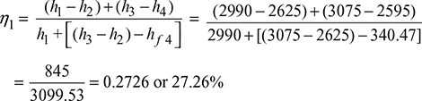
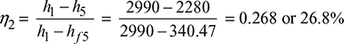
Efficiency of the cycle without reheating:
We know that efficiency of the cycle without reheating
Example 4.20
Steam supplied to a 10 MW turbo-alternator at 40 bar and 400°C. The auxiliaries consume 7% of the output. The condenser pressure is 0.05 bar and condensate is sub-cooled to 30°C. Assuming the boiler efficiency as 85%, the relative efficiency of turbine as 80%, and the mechanical efficiency of the alternator as 95%, determine (a) the steam consumption per hour, (b) the overall efficiency of the plant, and (c) the quality of steam at exit from turbine.
Solution
The h-s diagrams is shown in Fig. 4.35.
- From Mollier chart,h1 = 3215 kJ/kg, h2 = 2064 kJ/kgTherefore, (h1 − h2) = 3215 − 2064 = 1151 kJ/kgThus actual enthalpy drop,(h1 − h2) = ηrelative × (h1 − h2) = 0.8 × 1151 = 920.8 kJ/kgInput to the alternator =
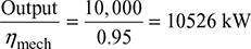
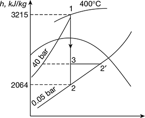 Figure 4.35 Mollier diagram for superheated steamTherefore, steam consumption per hour,
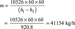
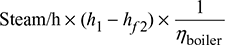
- Heat supplied to the boiler/hour =
 where hf2 = enthalpy of liquid at saturation at 0.05 bar from steam tablesThe auxiliaries consume 7% of the output.Therefore, useful output = (10,000 × 0.93) = 9300 kW = 9300 × 60 × 60 kJ/hThus overall efficiency =
- The dryness fraction at exit, that is, B′ is read at h2′ = 3215 − 920.8 = 2294.2 kJ on 0.05 bar line.Thus, x2′ = 0.889
Example 4.21
Two turbines, A and B, operate with steam at an initial pressure of 100 bar and temperature of 500°C. In each turbine, the steam is expanded in a high pressure turbine to 8.5 bar with efficiency ratio 80%. In turbine A, the expansion is further continued in low pressure turbine from 8.5 bar to 0.035 bar with efficiency ratio 0.75. In turbine B, steam is reheated after expansion in the high pressure turbine and is then fed to the low pressure unit at 7 bar and 500°C, after which it expands to 0.035 bar with efficiency ratio 0.85. Compare the two power cycle with respect to (a) thermal efficiency and (b) steam consumption for a full load output of 50,000 kW.
Solution
Turbine A: The expansion is shown on h-s chart in Fig. 4.36(a)
ha = 3377 kJ/kg and hb = 2753 kJ/kg
hc = hd = 3377 − 0.8 (3377−2753) = 2878 kJ/kg
he = 2060 kJ/kg
hf = hg = 2878 − (2878 − 2060) × 0.75 = 2264.5 kJ/kg
Total work done = (ha − hd) + (hd − hg) = (ha − hg)
= 3377 − 2264.5 = 1112.5 kJ/kg
Heat supplied = ha − hg
where hg is the sensible heat of steam at 0.035 bar = 110 kJ
∴ Heat supplied = 3377 − 110 = 3267 kJ
Thermal efficiency = ![]()
Total work to be done = 53,000 kW = 50,000 kJ/s
= 50,000 × 3600 kJ/h
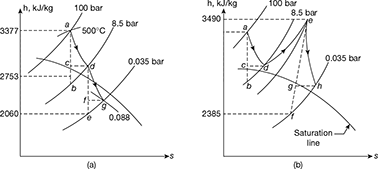
Figure 4.36 Mollier diagrams: (a) h-s diagram for Turbine A, (b) h-s diagram for Turbine B
∴ Steam consumption = ![]()
Turbine B: The expansion is shown on h–s chart in Fig. 4.36(b)
ha = 3377 kJ/kg: hb = 2753 kJ/kg; hc = hd = 2878 kJ/kg
he = 3490 kJ/kg; hf = 2385 kJ/kg.
hh = 3490 − (3490 − 2315) 0.85 = 2551 kJ/kg
Total work done = (3377 − 2878) + (3490 − 2551) = 1438 kJ/kg
Total heat supplied = (3377 − 110) + (3490 − 2878) = 3879 kJ/kg.
∴ Thermal efficiency ![]()
Steam consumption = ![]()
Example 4.22
In a regenerative cycle, having one feed water heater, the dry saturated steam is supplied from the boiler at a pressure of 30 bar and the condenser pressure is 1 bar. The steam is bled at a pressure of 5 bar. Determine the amount of bled steam per kg of steam supplied and the efficiency of the cycle. What would be the efficiency without regenerative feed heating? Determine the percentage increase in efficiency due to regeneration.
Solution
Given that p1 = 30 bar; p3 = 1 bar; p2 = 5 bar
From Mollier diagram, as shown in Fig. 4.37, we find that
Enthalpy of steam at 30 bar, h1 = 2800 kJ/kg
Enthalpy of steam at 5 bar, h2 = 2460 kJ/kg
Enthalpy of steam at 1 bar, h3 = 2220 kJ/kg
From steam tables, we also find the enthalpy or sensible heat of water at 5 bar.
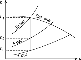
Figure 4.37 Mollier diagram for dry saturated steam
hf2 = 640.21 kJ/kg
and enthalpy or sensible heat of water at 1 bar,
hf3 = 417.44 kJ/kg
Amount of bled steam per kg steam supplied
We know that amount of bled steam per kg of steam supplied,
Efficiency of the cycle: We know that efficiency of the cycle,
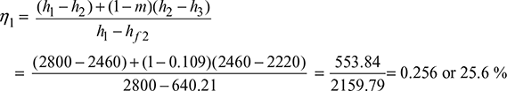
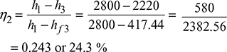
Efficiency of the cycle without regenerative feed heating: We know that efficiency of the cycle,
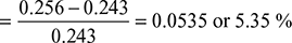
Percentage increase in efficiency due to regeneration: We know that percentage increase in efficiency due to regeneration
Example 4.23
In a steam turbine plant, the steam is generated and supplied to the turbine at 50 bar and 370°C. The condenser pressure is 0.1 bar and the steam enters the condenser with dryness fraction of 0.9. Two feed water heaters are used, the steam in the heaters being bled at 5 bar and 0.5 bar. In each heater, the feed water is heated to saturation temperature of the bled steam. The condensate is also pumped at this temperature into the feed line immediately after the heater. Find the masses of the steam bled in the turbine per one kg of steam entering the turbine. Assuming the condition line for the turbine to be straight, calculate the thermal efficiency of the cycle.
Solution
Given that p1 = 50 bar; T1 = 370°C; p4 = 0.1 bar; x4 = 0.9; p2 = 5 bar; p3 = 0.5 bar
First, let us draw the Mollier diagram and condition line for the cycle, as shown in Fig. 4.38. From this diagram, we find that,
h1 = 3110 kJ/kg, h2 = 2780 kJ/kg, h3 = 2510 kJ/kg, h4 = 2350 kJ/kg
From steam tables, we also find that
hf2 = 640.21 kJ/kg (at 5 bar)
hf3 = 340.47 kJ/kg (at 0.5 bar)
hf 4 = 191.81 kJ/kg (at 0.1 bar)
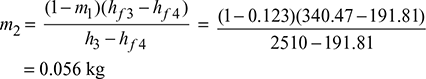
Mass of steam bled in the turbine:
We know that mass of steam bled at 2.
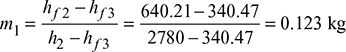
and mass of steam bled at 3.
Thermal efficiency of the cycle:
We know that work done from 1 to 2 per kg of feed water
= h1 − h2 = 3110 − 2780 = 330 kJ/kg
Similarly, work done from 2 to 3 per kg of feed water
= (1 − m1)(h2 − h3) = (1 − 0.123) (2780 − 2510) kJ/kg
= 236.8 kJ/kg
and work done from 3 to 4 per kg of feed water
= (1 − m1 − m2) (h3 − h4) = (1 − 0.123 − 0.056) (2510 − 2350) kJ/kg
= 131.4 kJ/kg
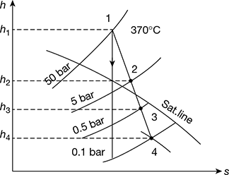
Figure 4.38 Mollier diagram
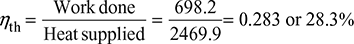
∴ Total work done = 330 + 236.8 + 131.4 = 698.2 kJ/kg
Heat supplied = h1 − hf2 = 3110 − 640.1 = 2469.9 kJ/kg
∴ Thermal efficiency of cycle,
Example 4.24
In the Rankine cycle, steam leaves the boiler and enters the turbine at 4 MPa and 400°C. The condenser pressure is 10 kPa. Neglecting pump work, determine the cycle efficiency and the Carnot efficiency for the same temperature limits.
Solution
Refer to Fig. 4.39. Rankine cycle is represented by 1−2−3−4 ignoring pump work, Carnot cycle for the same temperature limits may be reproduced by 1−2′−3′−4′.
Carnot efficiency is given by
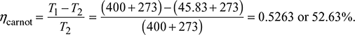
(It may be noted that Carnot efficiency is independent of the working substance.)
From steam tables, h1 at 4MPa and 400°C = 3213.5 kJ/kg, s1 = 6.7689 kJ/kg.K
At 10 kPa
hf = 191.81 kJ/kg, hfg = 2392.8 kJ/kg, sf = 0.6492 kJ/kg.K, sfg = 7.5010 kJ/kg.K
Also s1 = s2
or 6.7689 = 0.6492 + x2 × 7.5010
or ![]()
∴ h2 = hf3 + x2hfg = 191.81 + 0.816 × 2392.8 = 2144.33 kJ/kg
Thermal efficiency ηRankine =![]()
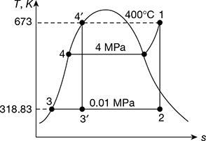
Figure 4.39 T-s diagram for Rankine cycle
Example 4.25
A steam power plant has the range of operation from 40 bar dry saturated to 0.05 bar. Determine (a) the cycle efficiency and (b) the work ratio and specific fuel consumption for (i) Carnot cycle and (ii) Rankine cycle.
Solution
From steam tables:
At 40 bar, tg = 250.4°C, vf = 0.001252 m3/kg, vg = 0.049778 m3/kg, hf = 1087.29 kJ/kg, hg = 2801.40 kJ/kg, sg = 6.07 kJ/kg.K
At 0.05 bar, tg = 32.88°C, vf = 0.0010005 m3/kg, vg = 28.193 m3/kg, hf = 137.79 kJ/kg
hfg = 2423.7 kJ/kg, sf = 0.4763 kJ/kg.K, sfg = 7.9187 kJ/kg.K
- Refer of Fig. 4.40. for Carnot cycle analysis on T-s plane.Cycle efficiency =
 (Note: Processes 1−2 and 3−4 are reversible adiabatic.)Also s1 = s2 = sf + x2sfgor
  Also s4 = s3 = sf + x3sfgor
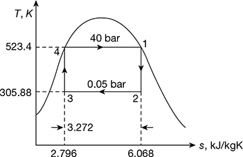 Figure 4.40 Carnot cycle on T-s plot
 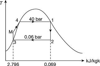 Figure 4.41 Rankine cycle on T-s plot∴ h2 = 137.79 + 0.706 × 2423.7 = 1848.9 kJ/kg.and h3 = 137.79 + 0.293 × 2423.7 = 847.9 kJ/kg.∴ ηCarnot cycle =
 Alternatively,
- Refer to Fig. 4.41 for Rankine cycle analysisPump work = hM − hf3
 = 0.001005 × 39.95 × 102 = 4.015 kJ/kgTherefore, net workwnet = h1 − h2 − wpump = 2801.4 − 1848.9 − 4.015 = 948.485 kJ/kgand ηRankine cycle =
 = 0.3566 or 35.66%
 - b. Also work ratio =
 Specific steam consumption/kWh
Example 4.26
Steam at 50 bar, 400°C expands in a steam tubine to 0.34 bar. For 150 kg/s of steam; determine (a) the power developed, (b) the thermal efficiency, and (c) the specific steam consumoption (i) for the Rankine cycle and (ii) for the Rankine engine. For an actual engine with same specifications, the brake steam rate is 4.75 kg/kWh and the driven electric generator has an electro mechanical efficiency of 94%.
Determine (a) the brake thermal efficiency, (b) the internal efficiency (expansion efficiency), (c) the power in kW, and (d) the exhaust dryness fraction of steam.
Solution
Refer to Fig. 4.42.
At 50 bar and 400°C
h1 = 3195.6 kJ/kg, s1 = 6.6458 kJ/kg.K, v1 = 0.05781 m3/kg
At 0.34 bar, hf = 301.48 kJ/kg, hfg = 2328.9 kJ/kg, sf = 0.9795 kJ/kg.K, sfg =6.7471 kJ/kg.K
And s1 = s2 for ideal expansion
6.6458 = 0.9795 + x2 ×6.7471
or x2 = 0.84
Thus h2 = hf3 + x2hfg = 301.43 + 0.84 × 2328.9 = 2257.756 kJ/kg
- For cycle wpump = Pump work = hM − hf3

- For engine
- Power developed = Steam per sec × (h1 − h2) = 150 × (3195.6 − 2257.756)= 140676.6 kW
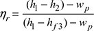
- ηRankine engine =
- Steam rate or specific steam consumption
- Actual engineBrake specific steam consumption = 4.75 kg/kWhηbrake thermal =
 Expansion efficiency =
 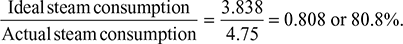 Actual enthalpy drop = 0.808 × Isentropic enthalpy drop= 0.808 (3195.6 − 2257.756) = 757.8 kJ/kgThus, h′2 = h1 − 757.8 = 3195.6 − 757.8 = 2437.8 kJ/kgAlso, h′2 = hf2 + xhfg2Thus,
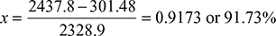
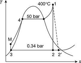 Figure 4.42 Rankine cycle on T-s plot
Example 4.27
In a steam power plant operating on Rankine cycle, the steam enters the turbine at 70 bar and 550°C with a velocity of 30 m/s. It discharges to the condenser at 0.20 bar with a velocity of 90 m/s. If the steam flow rate is 35 kg/s find the thermal efficiency and the net power produced. Neglect pump work.
Solution
Given that p1 = 70 bar, t1 = 550°C, c1 = 30 m/s, p2 = 0.20 bar, c2 = 90 m/s, ṁs = 35 kg/s
The simple Rankine cycle is shown in Fig. 4.43(a) and T-s diagram in Fig. 4.43(b).
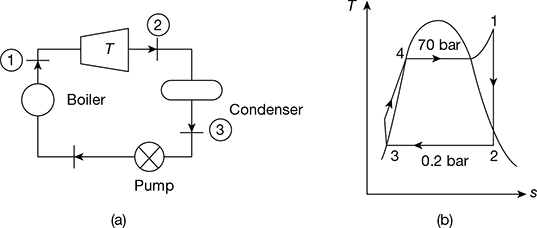
Figure 4.43 Rankine cycle: (a) Schematic diagram, (b) T-s diagram
At p1 = 70 bar and t1 = 550°C, h1 = 3530.9 kJ/kg, s1 = 6.9486 kJ/kg.K
At p2 = 0.2 bar, hf2 = 251384 kJ/kg, hfg2 = 2358.3 kJ/kg, sf2 = 0.8319 kJ/kg.K, sfg2 = 7.0766 kJ/kg.K
Now s1 = s2 = sf2 + x2 sfg2
or 6.9486 = 0.8319 + x2 × 7.0766
or x2 = 0.8644
∴ h2 = hf2 + x2 hfg2
= 251.38 + 0.8644 × 2358.3 = 2289.89 kJ/kg
Net power produced = ṁs (h1 − h2) = 35 (3530.9 − 2289.89) = 43435.35 kW
Thermal efficiency, ![]()
Now hf3 = hf2

Example 4.28
The following data refer to a steam turbine power plant employing one stage of regenerative feed heating:
State of steam entering HP stage: 10 MPa, 600°C
State of steam entering LP stage: 2 MPa, 400°C
State of steam at condenser : 0.01 MPa, x = 0.9
The correct amount of steam is bled for feed heating at exit the HP stage. Calculate the mass of steam bled per kg of steam passing through the HP stage and the amount of heat supplied in the boiler per second for an output of 10 MW. Neglect pump work.
Solution
The schematic diagram and T–s diagram are shown in Fig.4.44(a) and (b).
H.P. stage: p1 = 10 MPa, t1 = 600°C
L.P. stage: p2 = 2 MPa, t2 = 400°C
Condenser: p3 = 0.01 MPa, x3 = 0.9
Wout = 10 MW
From steam tables, we have (Fig. 4.44(a))
h1 = 3625.3 kJ/kg
h2 = 3247.6 kJ/kg
h3 = hf3 + x3 hfg3
= 191.81 + 0.9 × 2392.8 = 2345.35 kJ/kg
Heat balance for the heater:
(1 − m1) (h5 − h4) = m1(h2 − h5)
From steam tables,
h5 = 908.77 kJ/kg at p2 = 2 MPa
h4 = 191.81 kJ/kg at p3 = 0.01 MPa
∴ (1 − m1)(908.77 − 191.81) = m1(3247.6 − 908.77)
or (1 − m1) × 716.96 = 2338.83 m1
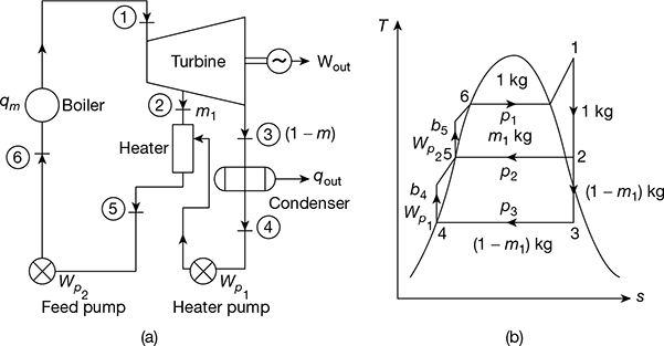
Figure 4.44 Regenerative feedwater heating cycle: (a) Schematic diagram, (b) T-s diagram
or ![]()
Heat supplied in boiler,
qin = h1 − h5 = 3625.3 − 908.8 = 2716.5 kJ/kg
Work output from boiler,
Wout = (h1 − h2) + (1 − m1) (h2 − h3)
= (3625.3 − 3247.6) + (1 − 0.235) (3247.6 − 2345.35) = 1067.92 kJ/kg
Cycle efficiency, ![]()
Heat supplied in the boiler for 10 MW output =![]()
Example 4.29
A small power plant produces 25 kg/s steam at 3 MPa, 600°C in the boiler. It cools the condenser with ocean water coming in at 12°C and returned at 15°C. Condenser exit is 45°C. Find (a) the net power output and (b) the required mass flow rate of ocean water.
Solution
Given that ṁs= 25 kg/s, p1 = 3 MPa, t1 = 600°C, twi = 12°C, two = 15°C, T1 = 600 + 273 = 873 K,T2 = 45 + 273 = 318 K
The T–s diagram is shown in Fig. 4.45.
- h1 = 3682 kJ/kg, hf3 = 188.4 kJ/kg, p1 = 9.5934 kPa, s1 = 7.5084 kJ/kg.Kvf3 = 0.00101 m3/kg, hfg3 = 2394.8 kJ/kgsf3 = 0.6386 kJ/kg.K, sfg3 = 7.5261 kJ/kg.KNow s1 = s2 = sf3 + x2 sfg3
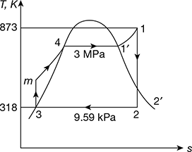 Figure 4.45 T-s diagramor 7.5084 = 0.6386 + x2 × 7.5261or x2 = 0.9128h2 = hf3 + x2 hfg3 = 188.42 + 0.9128 × 2394.8 = 2374.39 kJ/kgPump work, wp = vf3 (p1 − p2) = 0.00101 (300 − 9.59) = 0.29 kJ/kgTurbine work, wt = h1 − h2 = 3682.3 − 2374.39 = 1307.91 kJ/kgNet work, wnet = wt − wp = 1307.91 − 0.29 = 1307.62 kJ/kgNet power output = ṁs × wnet = 25 × 1307.62 = 32.69 MW
 - Heat rejected constant pressure p2, qr = h2 − hf3 = 2374.39 − 188.42 = 2185.97 kJ/kgLet ṁw = mass of ocean water circulatedṁwcpw × Δtw = ṁs× qror ṁw × 4.187 × (15 − 12) = 25 × 2185.97or ṁw = 4350.7 kg/s
Summary for Quick Revision
- The Rankine cycle is a vapour pressure cycle which operates on steam and is used for steam power plant. It consists of a boiler, turbine, condenser, and a pump.
- Net work, wnet = qa − qr= (h1 − hfM) − (h2 − hf 3) = (h1 − h2) − wp = wt − wpPump work, wp = hfM − hf3 = vf 3 (pM − p3) × 102 kJ/kg= vf 3 (p1 − p3) × 102 kJ/kg [∵ pM = p1]where vf is in m3/kg and p is in bar.
- Thermal efficiency of Rankine cycle considering pump work,
 Heat rate =
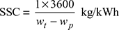
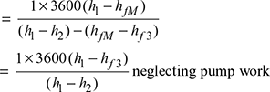
- Thermal efficiency of Rankine cycle neglecting pump work,

- Specific steam consumption,
- Overall heat rate, OHR = SSC × heat supplied per kg of throttle steam
- Back work ratio,
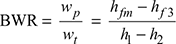 and work ratio,
- Increase of boiler pressure leads to increase in thermal efficiency of ideal Rankine cycle.
- Decrease in condenser pressure leads to increase in thermal efficiency of ideal Rankine cycle.
- Thermal efficiency of Rankine cycle can be improved by reheating and regeneration.
- Efficiency of reheat cycle, ηreheat=
- In the reheat cycle, steam is extracted at a suitable point after expanding in high pressure turbine and is reheated with the help of fl ue gases in the boiler furnace.
- Regeneration is a method to heat the feed water from the hot well of condenser reversibly by interchange of heat with the system to improve the cycle efficiency
- In open heaters, the bled steam is allowed to mix with feed water.
- In closed heaters, the bled steam is not allowed to mix with feed water. The feed water fl ows through the tubes in the heater and bled steam condenses on the outside of tubes.
- In a binary vapour cycle, two cycles with diff erent working fl uids are coupled in a series. Mercury is used in the topping cycle and steam in the bottoming cycle.
- In co-generation, some part of the expanded steam in the HP turbine is bled to generate electric power.
Leave a Reply