Reheating is mainly adopted to gain advantage of drier steam in the low pressure stages, and regeneration is adopted for increasing the thermal efficiency of the cycle. Therefore, it is advisable to execute cycle adopting both reheat and regeneration. Figure 4.22(a) shows the schematic diagram of such a cycle with two-stage regeneration and one-stage reheating at first bleeding point. The same cycle is represented on T-s diagram in Fig. 4.22(b).
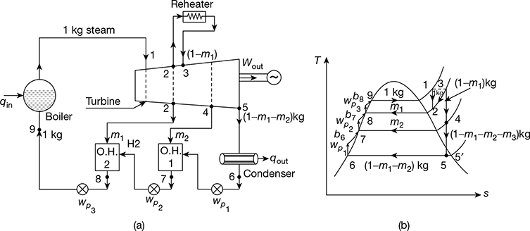
Figure 4.22 Reheat-regenerative cycle: (a) Schematic diagram, (b) T-s diagram
At point 2, m1 kg of steam is extracted from the turbine and is passed on to open heater 2 and the remaining (1 − m1) kg steam goes to reheater. The steam from the reheater comes back to the turbine at state point 3. Thereafter, (1 − m1) kg of steam expands from state point 3 to state point 4. At point 4, again m2 kg of steam is extracted and passed on to open heater 1. From state point 4, (1 − m1 − m2) kg of steam expands to condenser pressure state point 5, and further condenses in the condenser to water down to state point 6. Neglecting pump work, net work output from the prime mover is given by,
wout = (h1 − h2) + (1 − m1) (h3 − h4) + (1 − m1 − m2) (h4 − h5)
Net work of the cycle, wnet = wout − ∑wp
where ∑wp = wp1 + wp2 + wp3
= (1 − m1 − m2) (hb6 − h6) + (1 − m1) (hb7 − h7) + (hb8 − h8)
≃ vf6 (p1 − p6) × 102 kJ/kg
Heat added, qa = (h1 − hf8) + (1 − m1) (h3 − h2) − ∑wp
Thermal efficiency, ![]()
Leave a Reply