In the Rankine cycle and reheat, the condensate which is at a fairly low temperature is pumped to the boiler. Thus, there is an irreversible mixing of the cold condensate with hot boiler water. This results in loss of cycle efficiency. Regeneration is a method to heat the feed water from the hot well of the condenser reversibly by interchange of heat within the system, thus improving the cycle efficiency. The cycle is called regenerative cycle.
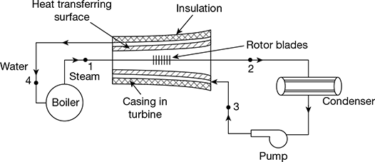
Figure 4.13 Regenerative heating
In Fig. 4.13, steam is drawn from the boiler at state point 1 and passes through the turbine and goes to the condenser at state point 2. If no heat is transferred from this steam to the surrounding, which include the casing, and the expansion is isentropic. This process is shown by line 1−2′ in the T-s diagram (Fig. 4.14). However, in the regenerative cycle, it is assumed that the condensate after being pumped to the boiler pressure at state point 4 passed through the hollow casing surrounding the turbine rotor to the boiler. Therefore, the steam losses heat to the surrounding water which gets heated. The temperature of steam entering the turbine and temperature of water leaving the turbine are same.
Let T1 = saturation temperature of steam at the commencement of expansion at state point 1.
T3 = temperature of saturated water condensate entering the hollow casing of turbine at state point 3. Thus, 1 kg of water is gradually heated along the path 3−4 and 1 kg of steam gradually loses the same amount of heat during expansion process 1−2. Such a heat exchange within the system is called regenerative heating. Therefore, the net heat supplied to the system is in the boiler during process 4−1 and the net heat rejected from the system is in the condenser during process 2−3 (Fig. 4.14).
Heat added, qa = T1 (s1 − s4)
Heat rejected, qr = T2 (s2 − s3)
Net work done,
wnet = qa − qr
= T1 (s1 − s4) − T2 (s2 − s3)
But s1 − s4 = s2 − s3
∴ wnet = (T1 − T2) (s1 − s4)
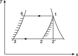
Figure 4.14 T-s diagram for regenerative Rankine cycle

This method of regeneration is not practicable because the steam becomes extremely wet at the later stages of expansion.
1 Regenerative Cycle with Open Heaters
The regeneration effect can be achieved by bleeding or extracting small quantities of steam at different points during the expansion and exploiting the energy of bled steam rather than whole steam. Thus, that part of the steam which continues to expand and to do work, does not condense excessively. A regenerative cycle with three bleeding points and therefore, three open type heaters, where feed water and steam mix, is shown in Fig. 4.15. The corresponding T-s diagram is shown in Fig. 4.16.
Let 1 kg of steam enter the turbine at state point 1 and expand to the state point 2 where m1 kg of steam is extracted from the turbine and passed on to the heater 3. The remainder (1 − m1) kg of steam continues to expand isentropically to state points 3 where m2 kg of steam is extracted and passed on the heater 2. The remainder (1 − m1 − m2) kg of steam further continues to expand isentropically to state point 4 where m3 kg of steam is bled and passed on to heater 1. Thus, only (1 − m1 − m2 − m3) kgof steam does the remaining isentropic expansion to point 5 before entering the condenser, where it is condensed to point 6. The condensate (1 − m1 − m2 − m3) kg at enthalpy b6 is mixed in heater 1. m3 kg of steam bled at state point 4 condenses to state point 7 and (1 − m1 − m2 −m3) kg of water gets heated from b6 to point 7. (1 − m1 − m2) kg of feed water at state point 7 is pumped to heater 2 at state point by. In the heater (1 − m1 − m2) kg of feed water is heated from state point 7 to state point 8 and m2 kg of bled steam from point 3 condenses to point 8. Thus, heater 2 has (1 − m1) kg of feed water at point 8 which is pumped to heater 3 raising the enthalpy of pumped feed water to b8. This feed water in heater 3 gets heated to point 9 by condensation of m1 kg of steam bled from point 2, leaving 1kg of feed water in heater 3 to be pumped to boiler pressure by raising its enthalpy to b9. Heating of 1 kg of feed water from b9 to point 10 is done in the boiler where it is further heated to steam at point 1.
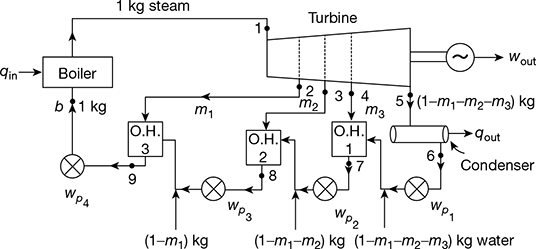
Figure 4.15 Regenerative feed water heating with open heaters
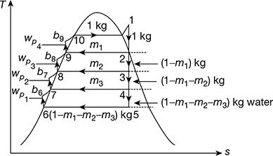
Figure 4.16 T-s diagram for feed heating with open heaters
For simplified analysis, points 6 and b6, 7 and b7, 8, and b8, 9 and b9 are treated as coincident points, thus ignoring the very small quantity of pump work. Thus, we have
Heat gained by feed water = Heat lost by bled steam
Heater 1: (1 − m1 − m2 − m3) (h7 − h6) = m3 (h4 − h7)
Heater 2: (1 − m1 − m2) (h8 − h7) = m2 (h3 − h8)
Heater 3: (1 − m1) (h9 − h8) = m1 (h2 − h9)
Net work output, wout = (h1 − h2) + (1 − m1) (h2 − h3) + (1 − m1 − m2) (h3 − h4) + (1 − m1 − m2 − m3)(h4 − h5)
wnet = wout − ∑wp
Heat added, qa = h1 − hb9 = h1 − h9 − wp4

Now ∑wp = (1 − m1 − m2 − m3) (hb6 − h6) + (1 − m1 − m2) (hb7 − h7) + (1 − m1) (hb8 − h8) + (hb9 − h9)
= vf6(p1 − p6)
where p1 = throttle pressure, p6 = condenser pressure and vf6 = specific volume of water at condenser pressure.
2 Regenerative Cycle with Closed Heaters
In this type of heater, the feed water is contained in the tubes about which the bled steam passes and condenses. One pump can be used for two or more heaters placed in series. The heaters can be placed in various combinations. One such arrangement is shown in Fig. 4.17. The corresponding T-s diagram is shown in Fig. 4.18.
Work done per kg of steam supplied to turbine,
wt = (h1 − h2) + (1 − m1) (h2 − h3) + (1 − m1 − m2) (h3 − h4)
Total pump work, ∑wp = wp1 + wp2 + wp3
= (1 − m1 − m2) (h6 − h5) + m2 (h10 − h9) + m1 (h12 − h11)
where h6 − h5 = vf5 (p1 − p4) × 102 kJ/kg
h10 − h9 = vf9 (p1 − p3) ×102 kJ/kg
h12 − h11 = vf11 (p1 − p2) × 102 kJ/kg
where vf is in m3/kg and p is in bar.
Now, vf5 = vf9 = vf11 = saturated volume of water
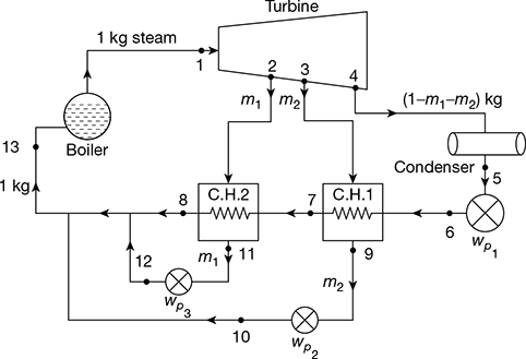
Figure 4.17 Regenerative feed water heating with closed heaters
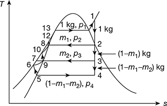
Figure 4.18 T-s diagram for regenerative Rankine cycle with closed heaters
Net work done, wnet = wt − ∑wp
Heat added in the boiler, qa = h1 − hf13

Neglecting heat losses and considering heat balance at feed heaters, we have
m2 (h3 − hf9) = (1 − m1 − m2) (hf9 − hf 5)
and m1 (h2 − hf11) = (1 − m1 − m2) (hf11 − hf9)
Neglecting enthalpy increase due to pump,
hf6 = hf5
also hf7 = hf9
and hf8 = hf11
The condition of feed water h13 entering the boiler is given by,
(1 − m1 − m2) hf11 + m2hf9 + m1hf11 = 1 × h13
or h13 = (1 − m2) hf11 + m2hf 9
Example 4.7
A boiler feeds a turbine at 56 bar and 600°C. Before being passed on to the condenser at 30°C, the steam is bled for regenerative feed heating at 6.5 bar. For an ideal regenerative cycle and 1kg/s of throttle steam, determine (a) the amount of bled steam, (b) net work done, and (c) the ideal efficiency of the cycle.
Solution
The T-s diagram is shown in Fig. 4.19.
At p1 = 56 bar, 600°C from steam tables,
h1 = 3659.5 kJ/kg, s1 = 7.2011 kJ/kg.K
At 6.5 bar, h2 = 2987 kJ/kg
and t2 = 265°C
s3 = s1 = sf3 + x3 sgh3
At 30°C, sf3 = 0.4369 kJ/kg.K, sfg3 = 8.01674 kJ/kg.K
or 7.2011 = 0.436 + x3 × 8.0164
or x3 = 0.8438
h3 = hf3 + x3hgh3 = 125.79 + 0.8438 × 2430.5 = 2176.6 kJ/kg
At 6.5 bar, hf6 = 684.26 kJ/kg, vf6 = 0.001104 m3/kg
h7 = hf6 + vf6 (p1 − p2) × 102 = 684.26 + 0.001104 (56 − 6.5) × 102
= 684.26 + 5.47 = 689.72 kJ/kg
wp2 = 5.47 kJ/kg
vf4 = 0.001004 m3/kg
p4 corresponding to 30°C = 0.042461 bar
wp1 = vf 4 (p2 − p4) = 0.001004(6.5 − 0.042461) × 102
= 0.648 kJ/kg
∑wp = wp1 + wp2 = 0.648 + 5.47 = 6.118 kJ/kg
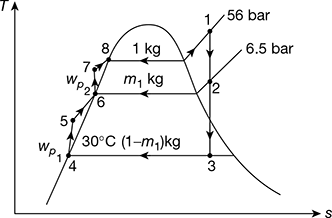
Figure 4.19 Regenerative Rankine cycle with a single heater
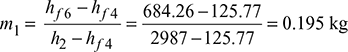
- Neglecting pump work, for heat balance of heater,m1 (h2 − hf6) = (1 − m1) (hf7 − hf4)
- wnet = wt − ∑wp = (h1 − h2) + (1 − m1) (h2 − h3) −∑wp = (3659.5 − 2987) + (1 − 0.195) (2987 − 2176.6) − 6.118 = 1318.754 kJ/kg
- Heat added, qa = (h1 − h7) = 3659.5 − 689.72 = 2969.78 kJ/kgCycle efficiency,
Example 4.8
Determine the improvement of efficiency which would results if a single stage of regenerative feed heating were added to a steam cycle having terminal conditions of 16 bar, 300°C and 0.05 bar. The steam for feed heating is to be extracted at 1.16 bar. The drain from the heat exchanger at saturation temperature of bled steam pressure is returned to the system at a point downstream from the heat exchanger, the feed water getting heated to saturation temperature at pressure of bled steam. Neglect change in enthalpy due to liquid pump work.
Solution
The regenerative cycle and h-s diagram is shown in Fig. 4.20(a) and (b).
From the Mollier diagram,
h1 = 3035 kJ/kg, h2 = 2575 kJ/kg, h3 = 2098 kJ/kg
From steam tables, hf1 = 856.6 kJ/kg, hf2 = 475.4 kJ/kg, hf3 = 137.8 kJ/kg
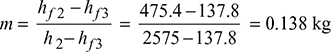
For heat balance of heater,
m (h2 − hf3) = (hf2 − hf3)
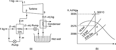
Figure 4.20 Single stage regenerative heating Rankine cycle: (a) Schematic diagram, (b) Mollier diagram
wnet = (h1 − h2) + (1 − m) (h2 − h3)
= (3035 − 2575) + (1 − 0.138) (2575 − 2098) = 871 kJ/kg
qa = h1 − hf2 = 3035 − 475.4 = 2559.6 kJ/kg
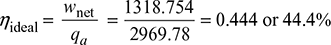
Thermal efficiency with regeneration, ![]()
Without feed water heating,
wnet = h1 − h3 = 3035 − 2098 = 937 kJ/kg
qa = h1 − hf3 = 3035 − 137.8 = 2897.2 kJ/kg
Thermal efficiency without regeneration, ![]()
Improvement in thermal efficiency = ![]()
Example 4.9
A regenerative cycle with three-stage bleed heating works between 30 bar, 450°C, and 0.04 bar. The bleed temperatures are chosen at equal temperature ranges. Determine the efficiency of the cycle. Neglect the pump work.
Solution
The schematic diagram of the cycle, T-s, and h-s diagrams are shown in Fig. 4.21(a) to (c).
At p = 0.04 bar, ts = 30°C
Temperature range = 450 − 30 = 420°C
Equal temperature difference = ![]()
The temperatures of bled steam are: 450 − 105 = 345°C, 240°C, 135°C
From Mollier chart,
h1 = 3340 kJ/kg, h2 = 3150 kJ/kg, h3 = 2935 kJ/kg,
h4 = 2720 kJ/kg, hs = 2120 kJ/kg
The pressure at 2, 3, 4 points are noted from the h–s chart. Then from steam tables,
hf1 = 1008.35 kJ/kg, hf2 = 837.45 kJ/kg, hf3 = 684.0 kJ/kg,
hf4 = 517.62 kJ/kg, hf5 = 121.4 kJ/kg
For heat balance of heaters,
m3 (h4 − hf4) = (1 − m1 − m2 − m3) (hf4 − hf5)
m2 (h3 − hf3) = (1− m1 − m2 − m3) (hf3 − hf4)
m1 (h2 − hf2) = (1 − m1) (hf2 − hf3)
∴ m3 (2720 − 517.62) = (1 − m1 − m2 − m3) (517.62 − 121.4)
or 2202.38 m3 = (1 − m1 − m2 − m3) × 396.22
m2 (2935 − 684) = (1 − m1 − m2) (684 − 517.62)
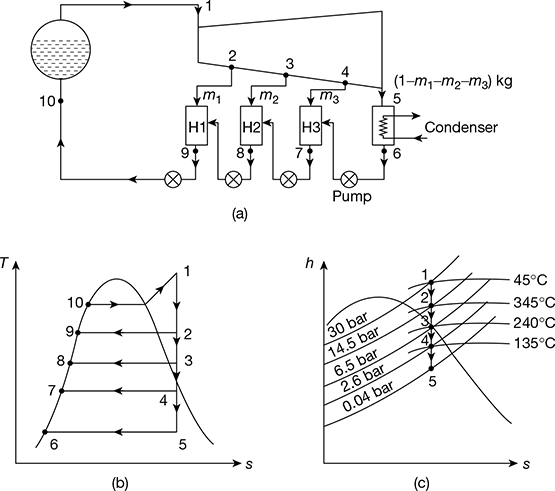
Figure 4.21 Regenerative Rankine cycle with three-stage bleeding: (a) Schematic diagram, (b) T-s diagram, (c) h-s diagram
or 2251 m2 = (1 − m1 − m2) × 166.38
m1 (3120 − 837.45) = (1 − m1) (837.45 − 684)
or 2282.55 m1 = (1 − m1) × 153.45
Solving the above three equations, we get
m1 = 0.063 kg, m2 = 0.0645 kg, m3 = 0.1332 kg
Net work done, wnet = 1 × (h1 − h2) + (1 − m1) (h2 − h3) + (1 − m1 − m2) (h3 − h4) + (1 − m1 − m2 − m3)(h4 − h5)
= (3340 − 3120) + (1 − 0.063) (3120 − 2935) + (1 − 0.063 − 0.0645) (2935 − 2720) + (1 − 0.063 − 0.0645 − 0.13327) (2720 − 2120) = 1024.6 kJ/kg
Heat added, qa = h1 − hf2 = 3340 − 837.45 = 2502.55 kJ/kg
Thermal efficiency of the cycle, ![]()
Leave a Reply