The purpose of steam generator control is to provide the steam flow required by the turbine at design pressure and temperate. The variables that are controlled are (i) fuel firing rate, (ii) air flow rate, (iii) gas flow distribution, (iv) feed-water flow rate, and (v) turbine valve-setting.
The key measurements that describe the plant performance are (i) steam flow rate, (ii) steam pressure, (iii) steam temperature, (iv) primary and secondary air flow rates, (v) fuel firing rate, (vi) feed-water flow rate, (vii) steam drum level, and (viii) electrical power output.
The control system must act on the measurement of these plant parameters so as to maintain plant operation at the desired conditions.
We shall discuss only a few basic control systems related to the following:
- Feed-water and drum level control: Feed water and steam flow are controlled to meet load demand by the turbine. Therefore, the level of water in the steam drum has to be maintained, normally half-full up to the diametral plane.A schematic diagram for the three-element feed-water control system is shown in Fig. 3.35. It comprises a drum-level sensor, feed-water flow sensor, and steam flow sensor.
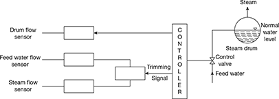 Figure 3.35 Schematic diagram for a three-element feed-water control system
 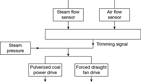 Figure 3.36 Schematic diagram of a steam pressure control system
 - Steam pressure control: A schematic diagram of steam pressure control system is shown in Fig. 3.36. It maintains the steam pressure by adjusting fuel and combustion air flow to meet the desired pressure. When pressure drops, the flows are increased. A steam pressure sensor acts directly on the fuel flow and air flow controls. A trimming signal from fuel flow and air flow sensors maintains the proper fuel-air ratio.
- Steam temperature control: For efficient power plant operation, an accurate control of superheat temperature of steam is essential. The principal variables affecting superheat temperature are (i) furnace temperature, (ii) cleanliness of radiant and pendant superheaters, (iii) temperature of gases entering the convective superheater, (iv) cleanliness of convective superheater, (v) mass flow rate of gases through the convective superheater, (vi) feed-water temperature, and (vii) variation of load on the unit.
A reduction in steam temperature results in loss in plant efficiency. On the other hand, a rise in steam temperature above design value may result in overheating and failure of superheater, reheater tubes, and turbine blades.
The temperature of the saturated steam leaving the drum corresponds to the boiler pressure and remains constant if the steam pressure controls are working properly. It is the superheater-reheater responses to load changes which need to be corrected. Some of the methods to correct them are as follows:
- Combined radiant-convective superheaters
- Desuperheating and attemperation
- Gas by-pass or damper control
- Gas recirculation
- Excess air
- Tilting burners
- Burner selection
- Separately fired superheater
3.16 ELECTROSTATIC PRECIPITATOR
The basic elements of an electrostatic precipitator are shown in Fig. 3.37. It comprises two sets of electrodes insulated from each other. The first set is composed of rows of electrically grounded vertical parallel plates, called the collection electrodes, between which the dust–laden gas flows. The second set of electrodes consists of wires, called the discharge or emitting electrodes that are centrally located between each pair of parallel plates. The wires carry a unidirectional negatively charged high voltage current from an external DC source. The applied high voltage generates a unidirectional, non-uniform electrical field whose magnitude is the greatest near the discharge electrodes. When that voltage is high enough, a blue luminous glow, called a corona, is produced around them. Electrical forces in the corona accelerate the free electrons present in the gas so that they ionise the gas molecules, thus forming more electrons and positive gas ions. The new electrons create again more free electrons and ions, which result in a chain reaction.
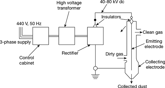
Figure 3.37 Basic elements of an electrostatic precipitator
The positive ions travel to the negatively charged wire electrodes. The electrons follow the electrical field toward the grounded electrodes, but their velocity decreases as they move away from the corona region around the wire electrodes towards the grounded plates. Gas molecules capture the low velocity electrons and become negative ions. As these ions move to the collecting electrode, they collide with the fly ash particles in the gas stream and give them negative charge. The negatively charged fly ash particles are driven to the collecting plate. Collected particulate matter is removed from the collecting plates on a regular schedule.
The arrangement of an electrostatic precipitator is shown in Fig. 3.38.
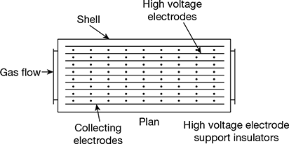
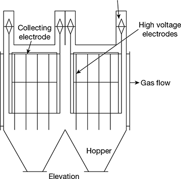
Figure 3.38 Arrangement of an electro
Leave a Reply