A boiler generates 4000 kg/h of steam at 20 bar, 400°C. The feed-water temperature is 50°C. The efficiency of the boiler is 80%. The calorific value of fuel used is 44,500 kJ/kg. The steam generated is supplied to a turbine developing 450 kW and exhausting at 2 bar with dryness fraction 0.96. Calculate the fuel burnt per hour and turbine efficiency. Also find the energy available in exhaust steam above 50°C.
Solution
From steam tables at 20 bar, 400°C, h1 = 3245.5 kJ/kg
Enthalpy of feed water at 50°C, hf = 209.3 kJ/kg
Fuel used per hour = ![]()
Enthalpy of exhaust steam at 2 bar, 0.96 dry,
h2 = hf2 + x2hfg2 = 504.7 + 0.96 × 2201.9 = 2618.5 kJ/kg
Enthalpy drop in turbine, ∆h = h1 − h2 = 3245.5 − 2618.5 = 627.0 kJ/kg
Energy available in the exhaust steam above 50°C = h2 − hf = 2618.5 − 209.3 = 2409.2 kJ/kg
Example 3.2
The following readings are taken during trial on a boiler for 1 h:
Steam generated = 5000 kg
Coal burnt = 650 kg
CV of coal = 31,500 kJ/kg
Dryness fraction of steam entering the superheater = 0.90
Rated boiler pressure = 10 bar
Temperature of steam leaving the superheater = 250°C
Temperature of hot well = 40°C
Calculate: (a) equivalent evaporation per kg of fuel without and with superheater, (b) thermal efficiency of the boiler without and with superheater, and (c) amount of heat supplied by the superheater per hour.
Solution
Given that ms = 5000 kg/h, mf = 650 kg/h, C.V. of fuel = 31,500 kJ/kg, x = 0.90, p = 10 bar
Equivalent evaporation, ![]()
where ms = mass of steam generated per kg of fuel = ![]()
- Without superheater,
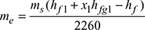 At 10 bar, hf 1 = 762.8 kJ/kg, hfg1 = 2015.3 kJ/kgAt 40°C, hf = 167.6 kJ/kg
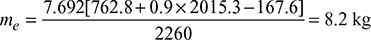 With superheater,
 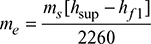 At 10 bar, 250°C, hsup = 2942.6 kJ/kg
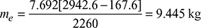
- Thermal efficiency,
 Without superheater,
  With superheater,
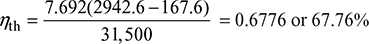
- Heat supplied by the superheater per hour = ms [(1 − x)hfg1 + hsup]= 5000 [(1 − 0.9) × 2015.3 + 2942.6] = 15,720,650 kJ/h
Example 3.3
The following data refer to a boiler trial:
Feed water = 700 kg/h
Feed-water temperature = 25°C
Steam pressure = 15 bar
Steam temperature = 300°C
Coal burnt = 90 kg
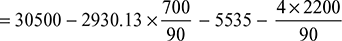
CV of coal = 30,500 kJ/kg
Ash and unburnt coal in ash pit = 4 kg/h with C.V. = 2200 kJ/kg
Flue gas formed = 20 kg/kg of coal burnt
Flue gas temperature at chimney = 300°C
Ambient temperature = 30°C
Mean specific heat of flue gases = 1.025 kJ/kgK
Calculate (a) the boiler efficiency, (b) the equivalent evaporation, and (c) the percentage heat unaccounted for.
Solution
From steam tables, at 15 bar, 300°C, hsup = 3038.9 kJ/kg
At 25°C, hf = 108.77 kJ/kg
Heat absorbed by 1 kg of feed water to transform into steam at 300°C and 15 bar
= hsup − hf = 3038.9 − 108.77 = 2930.13 kJ/kg
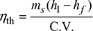
- Boiler efficiency,
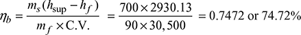
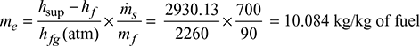
- Equivalent evaporation,
 Heat carried away by flue gases = mg cpg (Tg − Ta)= 20 × 1.025 × (300 − 30) = 5535 kJ/kg of coal
 - Heat unaccounted for per kg of fuel= CV of fuel − heat in steam − heat in flue gases − heat in ash pit
 = 30500 − 22790 − 5535 − 97.8 = 2077.2 kJ/kg
Example 3.4
The following observations were made during a boiler trial:
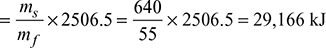
Mass of feed water and its temperature = 640 kg/h, 50°C
Steam pressure = 10 bar
Fuel burnt = 55 kg/h
HCV of fuel = 44,100 kJ/kg
Temperature of flue gases = 300°C
Boiler house temperature = 30°C
Dryness fraction of steam = 0.97
Heating surface of boiler = 18.6 m2
Specific heat for flue gases = 1.1 kJ/kgK
Specific heat for superheated steam = 2.1 kJ/kgK
Composition of liquid fuel used by mass: C = 85%, H2 = 13%, and ash = 2%
The flue gas analysis by volume done by using Orsat apparatus:
CO2 = 12.5%, O2 = 4.5%, and N2 = 83%
Calculate (a) the equivalent evaporation per kg of fuel per m2 of heating surface area per hour, (b) the boiler efficiency, and (c) the draw the heat balance sheet on 1 kg of fuel basis. Take the partial pressure of steam in exhaust gases = 0.07 bar.
Solution
- Equivalent evaporation,
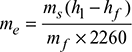 h1 = hf1 + x1hfg1At 10 bar, hf1 = 762.6 kJ/kg, hfg1 = 2013.6 kJ/kgFor feed water at 50°C, hf = 209.3 kJ/kg
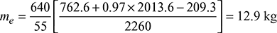
- Boiler efficiency,
- Heat used to generate steam per kg of fuel
 Air supplied per kg of fuel burnt =
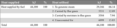
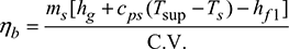
 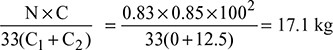 Dry flue gases formed per kg of fuel burnt = 17.1 + 0.85 = 17.95 kgHeat carried by dry flue gases = mg × cpg (Tg − Ta)= 17.95 × 1.1 (300 − 30) = 5331 kJ/kg of fuelMoisture formed per kg of fuel = 0.13 × 9 = 1.17 kgHeat carried by moisture in the flue gases per kg of fuel= 1.17 [hg + cps (Tsup − Ts) − hf] at 0.07 bar= 1.17 [2572.6 + 2.1 (300 − 39) − 125.8]= 3504 kJHeat unaccounted for = 44,100 − (29,166 + 5331 + 3504) = 6099 kJ
Heat balance sheet:
Example 3.5
The following data was recorded during a boiler trial for 1 h:
Steam generated = 4500 kg, Steam pressure = 10 bar gauge
Record of throttling calorimeter:
Steam pressure = 30 mm of Hg above barometer reading.
Steam temperature = 105°C
Barometer reading = 735 mm of Hg
Specific heat of superheated steam = 2.1 kJ/kgK
Feed-water temperature = 58°C
Temperature of steam leaving the superheater = 202°C
Coal fired = 450 kg, HCV of coal = 35,700 kJ/kg
Flue gas temperature = 260°C, Boiler house temperature = 30°C
Ultimate analysis of dry coal:
C = 82 %, H2 = 14 %, and ash = 4%
Volumetric analysis of dry flue gases by Orsat apparatus:
CO2 = 12 %, CO = 1.5 %, O2 = 7%, N2 = 79.5 %
Specific heat of dry flue gases = 1.0 kJ/kgK
Partial pressure of steam going with flue gases = 0.07 bar
Moisture content of coal at the time of feeding into the boiler = 4%
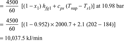
- Calculate the heat absorbed by the superheater per minute.
- Draw up the heat balance sheet on the basis of 1 kg of wet coal fired.
Solution
Quality of steam generated by the boiler:
Pressure of steam after throttling = ![]()
Absolute pressure of steam generated = ![]()
Total heat in steam before throttling at 10.98 bar = Total heat in steam after throttling at 1.02 bar
hf1 + x1 hfg1 = (hf2 + hfg2) + cps (Tsup2 − Ts2)
or 780.936 + x1 × 2000.7 = 2675.696 + 2.1 (105 − 100)
or x1 = 0.952
Heat absorbed in the superheater per minute:
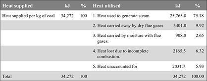
Heat generated per kg of coal fired:
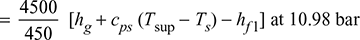
- Hg = Content of dry coal × HCV= (1 − 0.04) × 35,700 = 34,272 kJ/kg
- Heat absorbed in boiler and superheater per kg of coal to generate steam
 = 10 [2781.6 + 2.1 (202 − 184) − 4.187 × 58] = 25,765.8 kJ/kg
 - Air supplied per kg of coal burned
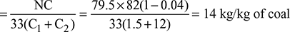 Dry flue gases formed per kg of coal fired= 14 + (1 − 0.04) × 0.82 = 14.787 kg/kg of coal
 - Heat carried away by dry flue gases per kg of coal burned= 14.787 × 1.0 (260 − 30) = 3401.0 kJ/kg of coal
- Moisture carried away by flue gases per kg of coal burned= Moisture in the fuel + Moisture formed due to combustion of H2
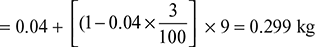 Heat carried by moisture going with flue gases= 0.299 [hg + cps (Tsup − Ts)] at 0.07 bar= 0.299 [2572.6 + 2.1 (260 − 39)] = 908 kJ
 - Part of carbon burnt to CO =
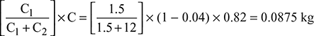 C.V. when C burns to CO2 = 35,000 kJ/kg, and when burns to CO = 10,250 kJ/kgHeat lost due to incomplete combustion = 0.0875 (35,000 − 10,250)= 2165.5 kJ/kgHeat balance sheet on the basis of 1 kg of coal burned is as follows:
Example 3.6
A power plant producing 125 MW of electricity has steam condition at boiler outlet as 110 bar, 500°C and condenser pressure is 0.1 bar. The boiler efficiency is 92 % and consumes coal of calorific value 25 MJ/kg. The feed-water temperature at boiler inlet is 150°C. The steam generator has risers in the furnace wall 30 m high and unheated downcomers. The quality at the top of the riser is 8.5 % and minimum exit velocity of mixture leaving the riser and entering the drum is required to be 2 m/s. The risers have 50 mm outside diameter and 3 mm wall thickness. Neglecting pump work and other losses, estimate (a) the steam generation rate, (b) the fuel burning rate, (c) the evaporation factor, (d) the pressure head available for natural circulation, (e) the circulation ratio, (f) the number of risers required, and (g) the heat absorption rate per unit projected area of the riser.
Solution
Refer Fig. 3.34.
Given that P = 125 MW, p1 = 110 bar, t1 = 500°C, p2 = 0.1 bar, ve = 2 m/s
ηb = 92 %, C.V. = 25 MJ/kg, tfw = 150°C, xtop = 0.085
From steam tables:
At p1 = 110 bar, 500°C, h1 = 3361 kJ/kg, s1 = 6.540 kJ/kgK
p2 = 0.1 bar, hf2 = 191.83 kJ/kg, hfg2 = 2392.8 kJ/kg
sf2 = 0.6493 kJ/kgK, sfg2 = 7.5009 kJ/kgK
At tfw = 150°C, hf5 = 632.2 kJ/kg
s1 = s2 for isentropic process
6.540 = 0.6493 + x2 × 7.5009
or x2 = 0.7853
h2 = hf2 + x2 hfg2 = 191.83 + 0.7853 × 2392.8 = 2070.89 kJ/kg
h3 = h4 = hf2 = 191.83 kJ/kg
- Let ṁs = mass flow rate of steam in kg/sThen ṁs (h1 − h2) = Por ṁs (3361 − 2070.89) = 125 × 103or ṁs = 96.89 kg/s
- Boiler efficiency,
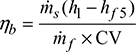
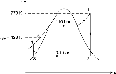 Figure 3.34 Temperature-entropy diagramor
 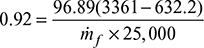 Rate of fuel burned, ṁf = 11.495 kg/s
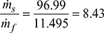
 - Evaporation factor =
- Pressure head available for natural circulation,∆p = gH (ρf − ρm)At 110 bar, vf = 0.001489 m3/kg, vf = 0.015987 m3/kgvtop = 0.001489 + 0.085 (0.015987 − 0.001489) = 0.002721 m3/kg
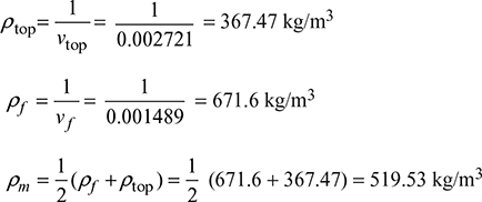 ∆p = 30 × 9.81 (671.6 − 519.53) = 44.754 kPa or 0.44754 bar
 - Circulation ratio, CR =
- di = d0 − 6 = 50 − 6 = 44 mmRate of steam formation in riser,
 Number of risers =
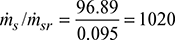
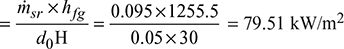
- At 110 bar, hfg = 1255.5 kJ/kg from steam tables.Heat absorption rate per unit projected area of the riser
Example 3.7
An oil fired boiler uses 52 kg/h of oil having an HCV of 44,900 kJ/kg and composition/kg: C = 0.847, H2 = 0.13, S = 0.0125, and generates 635 kg of steam/h at 10.5 bar pressure from feed water supplied at 338 K. The flue gases having dry gas analysis/unit volume: O2 = 0.043, CO2 = 0.124, N2 = 0.833, and specific heat 1.005 kJ/kg-K, leave the boiler at 635 K. The pressure and temperature of steam after throttling in a throttling calorimeter is 1.15 bar and 398 K, respectively. Taking the partial pressure of steam in flue gases as 0.07 bar and the specific heat of superheated steam = 2.1 kJ/kg-K, determine (a) the equivalent evaporation/kg of fuel and (b) boiler efficiency.
Draw up a complete heat balance sheet. Take boiler room temperature = 234 K. [IES, 2000]
Solution
Given: ṁf = 52 kg/h, HCV = 44,900 kJ/kg, ṁs = 635 kg/h, p1 = 10.5 bar,
Tf = 338 K, p2 = 1.15 bar, Tsup = 398 K, pvs = 0.07 bar, Tg = 635 K,
Ta = 234 K, cps = 2.1 kJ/kgK, cpg = 1.005 kJ/kgK,
Fuel: C = 0.847, H2 = 0.13, S = 0.0125 per kg
Flue gas: O2 = 0.043, CO2 = 0.124, N2 = 0.833
Throttling calorimeter:
hf1 + x1 hfg1 = hf2 + hfg2 + cps (Tsup − Ts2)
From steam tables, we have
At p1 = 10.5 bar, hf1 = 772.2 kJ/kg, hfg1 = 2007.7 kJ/kg
At p2 = 1.15 bar, hf2 = 434.0 kJ/kg, hfg2 = 2247.5 kJ/kg, ts2 = 102.05°C
or Ts2 = 375.05 K
772.2 + x1 × 2007.7 = 434.0 + 2247.5 + 2.1 (398 − 375.02) = 2729.76
or ![]()
Dryness fraction of steam = 0.975
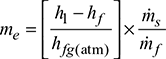
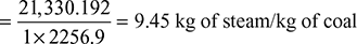
- Equivalent evaporation:h1 = hf1 + x1 hfg1 = 772.2 + 0.975 × 2007.7 = 2729.7 kJ/kgAt Tf = 338 K, hf = cpw (Tf − 273) = 4.187 (338 − 273)= 272.1 kJ/kghfg(atm) = specific enthalpy of evaporation at standard atmospheric pressure of 1.01325 bar = 2256.9 kJ/kgEquivalent evaporation,
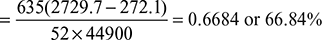
- Boiler efficiency,
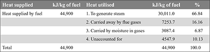
 Heat balance sheet
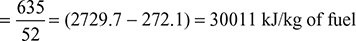
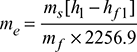
- Heat used to generate steam per kg of fuel =

- Air supplied per kg of fuel burned =

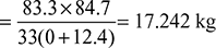 Dry flue gases formed per kg of fuel burned, mg = 17.242 + 0.847 = 18.089 kgHeat carried away by dry flue gases = mg × cpg (Tg − Ta)= 18.089 × 1.005 (635 − 234) = 7253.7 kJ/kg of fuel
 - Moisture formed per kg of fuel, mw = 0.13 × 9 = 1.17 kgHeat carried away by moisture in flue gases per kg of fuel= mw [hg + Cps (Tsup − Ts) − hf] at p = 0.07 bar= 1.17 [2572.5 + 2.1 (635 − 312) − 163.4] [∴ Ts = 39°C at 0.07 bar]= 3087.4 kJ/kg of fuel
- Heat un-accounted for = 44,900 − (30,011 + 7253.7 + 3087.4)= 4547.9 kJ/kg of fuel
- Heat used to generate steam per kg of fuel =
Example 3.8
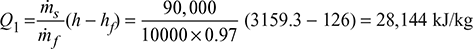
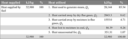
During a boiler trial, steam was produced at a pressure of 20 bar and superheat temperature of 360°C using feed water at 30°C at the rate of 90000 kg/h. Coal with 3% moisture having calorific value of 34000 kJ/kg of dry coal was burnt at the rate of 1000 kg/h. The temperature of flue gases at the exit was 200°C, whereas inlet air was at 30°C. Coal contains 80% carbon, 6% hydrogen, and rest ash. Volumetric analysis of dry flue gases is: CO2 = 12 %, O2 = 10% and N2 = 78 %. Enthalpy of steam at 20 bar, 360° C = 3159.3 kJ/kg, enthalpy of water at 30°C = 126 kJ/kg. In the flue gas, the enthalpy of steam at exit condition is 2879.7 kJ/kg. Specific heat of gas = 1.01 kJ/kg.
Draw the heat balance sheet.
[IES, 1998]
Solution
Steam condition: 20 bar, 360°C
Feed water: 30°C, 90,000 kg/h
Moisture in coal = 3 %, CV of coal = 34000 kJ/kg of dry coal, ṁf = 1000 kg/h
Exhaust temperature of flue gases = 200°C
Inlet temperature of air = 30°C
Coal composition: C = 80 %, H2 = 6 %, rest is ash.
Volumetric analysis of dry flue gases:
CO2 = 12%, O2 = 10 %, N2 = 78 %
Enthalpy of steam at 20 bar, 360°C = 3159.3 kJ/kg
Enthalpy of water at 30°C = 126 kJ/kg
Enthalpy of steam in flue gases at exit = 2879.7 kJ/kg
Specific heat of gas = 1.01 kJ/kg
Heat supplied by coal per kg, Q = (1 − 0.03) C.V. = (1 − 0.03) × 34,000 = 32,980 kJ/kg
Heat used to generate steam per kg of fuel,
Air supplied per kg of fuel burnt = ![]()
Dry flue gases formed per kg of fuel burned, mg = 15.76 + 0.80 = 16.56 kg
Heat carried away by dry flue gases, Q2 = mg × cpg (Tg − Ta)
= 16.56 × 1.01 (200 − 30) = 2843.3 kJ
Moisture formed per kg of fuel = 0.06 × 9 = 0.54 kg
Heat carried away by moisture in flue gases, Q3 = 0.54 × 2879.7 = 1555 kJ
Heat lost to moisture in coal, Q4 = 0.03 × 2879.7 = 86.39 kJ
Q1 + Q2 + Q3 + Q4 = 28,144 + 2843.3 + 1555 + 86.39 = 32628.69 kJ
Heat unaccounted for, Q5 = 32980 − 32628.69 = 351.31 kJ
3.15 STEAM GENERATOR CONTROL
The purpose of steam generator control is to provide the steam flow required by the turbine at design pressure and temperate. The variables that are controlled are (i) fuel firing rate, (ii) air flow rate, (iii) gas flow distribution, (iv) feed-water flow rate, and (v) turbine valve-setting.
The key measurements that describe the plant performance are (i) steam flow rate, (ii) steam pressure, (iii) steam temperature, (iv) primary and secondary air flow rates, (v) fuel firing rate, (vi) feed-water flow rate, (vii) steam drum level, and (viii) electrical power output.
The control system must act on the measurement of these plant parameters so as to maintain plant operation at the desired conditions.
We shall discuss only a few basic control systems related to the following:
- Feed-water and drum level control: Feed water and steam flow are controlled to meet load demand by the turbine. Therefore, the level of water in the steam drum has to be maintained, normally half-full up to the diametral plane.A schematic diagram for the three-element feed-water control system is shown in Fig. 3.35. It comprises a drum-level sensor, feed-water flow sensor, and steam flow sensor.
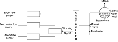 Figure 3.35 Schematic diagram for a three-element feed-water control system
 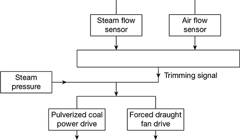 Figure 3.36 Schematic diagram of a steam pressure control system
 - Steam pressure control: A schematic diagram of steam pressure control system is shown in Fig. 3.36. It maintains the steam pressure by adjusting fuel and combustion air flow to meet the desired pressure. When pressure drops, the flows are increased. A steam pressure sensor acts directly on the fuel flow and air flow controls. A trimming signal from fuel flow and air flow sensors maintains the proper fuel-air ratio.
- Steam temperature control: For efficient power plant operation, an accurate control of superheat temperature of steam is essential. The principal variables affecting superheat temperature are (i) furnace temperature, (ii) cleanliness of radiant and pendant superheaters, (iii) temperature of gases entering the convective superheater, (iv) cleanliness of convective superheater, (v) mass flow rate of gases through the convective superheater, (vi) feed-water temperature, and (vii) variation of load on the unit.
A reduction in steam temperature results in loss in plant efficiency. On the other hand, a rise in steam temperature above design value may result in overheating and failure of superheater, reheater tubes, and turbine blades.
The temperature of the saturated steam leaving the drum corresponds to the boiler pressure and remains constant if the steam pressure controls are working properly. It is the superheater-reheater responses to load changes which need to be corrected. Some of the methods to correct them are as follows:
- Combined radiant-convective superheaters
- Desuperheating and attemperation
- Gas by-pass or damper control
- Gas recirculation
- Excess air
- Tilting burners
- Burner selection
- Separately fired superheater
3.16 ELECTROSTATIC PRECIPITATOR
The basic elements of an electrostatic precipitator are shown in Fig. 3.37. It comprises two sets of electrodes insulated from each other. The first set is composed of rows of electrically grounded vertical parallel plates, called the collection electrodes, between which the dust–laden gas flows. The second set of electrodes consists of wires, called the discharge or emitting electrodes that are centrally located between each pair of parallel plates. The wires carry a unidirectional negatively charged high voltage current from an external DC source. The applied high voltage generates a unidirectional, non-uniform electrical field whose magnitude is the greatest near the discharge electrodes. When that voltage is high enough, a blue luminous glow, called a corona, is produced around them. Electrical forces in the corona accelerate the free electrons present in the gas so that they ionise the gas molecules, thus forming more electrons and positive gas ions. The new electrons create again more free electrons and ions, which result in a chain reaction.
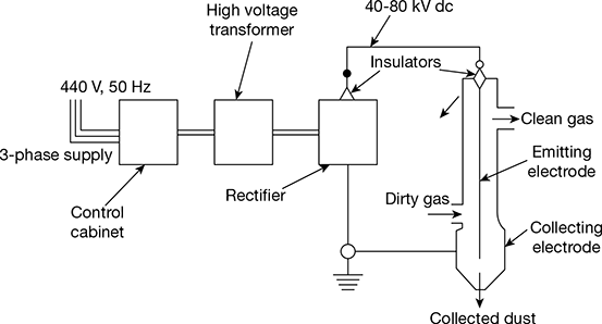
Figure 3.37 Basic elements of an electrostatic precipitator
The positive ions travel to the negatively charged wire electrodes. The electrons follow the electrical field toward the grounded electrodes, but their velocity decreases as they move away from the corona region around the wire electrodes towards the grounded plates. Gas molecules capture the low velocity electrons and become negative ions. As these ions move to the collecting electrode, they collide with the fly ash particles in the gas stream and give them negative charge. The negatively charged fly ash particles are driven to the collecting plate. Collected particulate matter is removed from the collecting plates on a regular schedule.
The arrangement of an electrostatic precipitator is shown in Fig. 3.38.
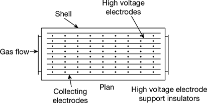
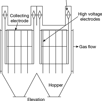
Figure 3.38 Arrangement of an electrostatic precipitator
Example 3.9
A boiler generates 8 kg of steam per kg of coal burnt at a pressure of 10 bar, from feed water having a temperature of 65°C. The efficiency of the boiler is 75% and factor of evaporation 1.2. Specific heat of steam at constant pressure is 2.2 kJ/kgK. Calculate (a) the degree of superheat and temperature of steam generated, (b) the calorific value of coal used in kJ/kg, and (c) the equivalent evaporation in kg of steam per kg of coal.
Solution
Given: ms = 8 kg/kg of coal, ps = 10 bar, tfw = 65°C, ηb = 75%, Fe = 1.2, cps = 2.2 kJ/kgK
- At p = 10 bar, from steam tables:hg = 2778.1 kJ/kg, Ts = 273 + 179 = 452 KAlso, hf1 = cpw tfw = 4.187 × 65 = 272.155 kJ/kg of feed waterhfg = 2256.9 kJ/kg at atmospheric pressure.Factor of evaporation,
 or
or 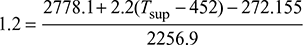 or 2708.28 = 2505.945 + 2.2 (Tsup − 452)or Tsup = 543.97 K or tsup = 270.97°CDegree of superheat = Tsup − Ts = 543.97 − 452 = 91.97°C
 - Boiler efficiency,
 or 0.75 =
 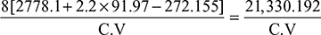 or C.V. = 28,440 kJ/kg of coal
 - Equivalent evaporation,
Example 3.10
The following observations were made during the trial of a gas-fired boiler of a steam power plant:
Generator output = 50,000 kW
Steam conditions = pressure 50 bar temperature 500°C
Feed-water temperature = 80°C
Steam output = 65 kg/s
Percentage composition of fuel (natural gas), by volume CH4 = 96.5, C2H6 = 0.5 (rest incombustibles)
HCV of gas = 38,700 kJ/m3, at 1.013 bar and 15°C
Gas consumption = 6.5 m3/s
Calculate the boiler efficiency and the overall thermal efficiency based on the lower calorific value of the fuel.
[IES, 1996]
Solution
Combustion equations:
CH4 + 2O2 → CO2 + 2H2O
C2H6 + 2.5O2 → 2CO2 + 3H2O
1 mole of CH4 burns to give 2 moles of water
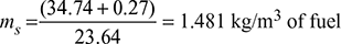
Therefore, 0.965 moles give 2 × 0.965 × 18 = 34.74 kg of H2O
Similarly 0.005 moles of C2H6 burns to give 3 × 0.005 × 18 = 0.27 kg of H2O
Assuming steam as a perfect gas, 1 mole of gas at 1.013 bar and OC is 22.41 m3
∴ 1 mole of gas at 15°C = ![]()
Mass of steam produced,
HCV = LCV + heat in steam
HCV = 38,700 − ms hfg at 15°C
= 38,700 − 1.481 × 2465.9 [hfg at 15°C = 2465.9 kJ/kg]
= 35,043.07 kJ/kg
At 50 bar and 500°C, h1 = 3433.8 kJ/kg
At 80°C, hfg for feed water = 334.98 kJ/kg
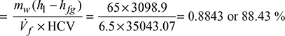
Enthalpy of steam = h1 − hfg = 3433.8 − 334.9 = 3098.9 kJ/kg
Boiler efficiency = ![]()
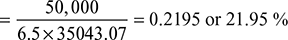
Overall thermal efficiency = ![]()
Example 3.11
In a trial on a boiler fitted with an economiser, the following results were obtained:
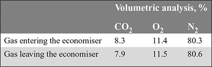
The fuel contains 80 % carbon and it does not contain nitrogen.
Calculate (a) the air leakage into the economiser per minute if the fuel used in the boiler is 60 kg/min. (b) the reduction in temperature of the gas due to air leakage if the atmospheric air temperature is 20°C and the flue gas temperature is 350°C.
For air: specific heat, cpa = 1.005 kJ/kgK and for gas, cpg = 1.1 kJ/kgK.
Percentage of incombustible in fuel = 15%
Solution
Air supply per kg of fuel for the gas analysis entering the economiser,
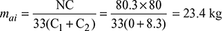
Air supply per kg of fuel for the gas analysis leaving the economiser,
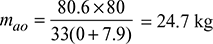
Air leakage into the economiser per kg of fuel burned in boiler
= mao − mai = 24.7 − 23.4 = 1.3 kg
Air leakage in the economiser per minute = 1.3 × 60 = 78 kg
Mass of flue gas products formed per kg of coal = 23.4 + (1 − 0.15) = 24.25 kg
∴ cpg mg Tg + cpa ma Ta = cpg (mg + ma) Tm
where Tm = temperature of exhaust gases leaving the economiser
1.1 × 24.25 × 623 + 1.005 × 1.3 × 293 = 1.1 (24.25 + 1.3) × Tm
or Tm = 604.9 K or 331.9°C
Drop in temperature of exhaust gases due to air leakage into the economiser
= 350 − 331.9 = 18.1°C
3.17 DRAUGHT
In order to maintain the continuous flow of fresh air into the combustion chamber, it is necessary to exhaust the products of combustion from the combustion chamber of a boiler. A pressure difference has to be maintained to accelerate the products of combustion to their final velocity and to overcome the pressure losses in the flow system. This pressure difference so maintained is called “draught”.
1 Classification of Draught
The method of producing draught may be classified as follows:
- Natural (or chimney) draught
- Artificial draught
- Steam jet draught
- Induced draught
- Forced draught
- Mechanical draught
- Induced fan draught
- Forced fan draught
- Balanced draught
- Steam jet draught
2 Natural Draught
Natural draught is obtained by the use of a chimney. A chimney is a vertical tubular structure of brick, masonry, steel, or reinforced concrete, built for the purpose of enclosing a column of hot gases, to produce the draught. The draught produced by the chimney is due to the density difference between the column of hot gases inside the chimney and the cold air outside.
A diagrammatic arrangement of a chimney of height H in m above the grate is shown in Fig. 3.39.
Pressure at the grate level on the chimney side,
p1 = patm + γgh
where patm = atmospheric pressure at the chimney top
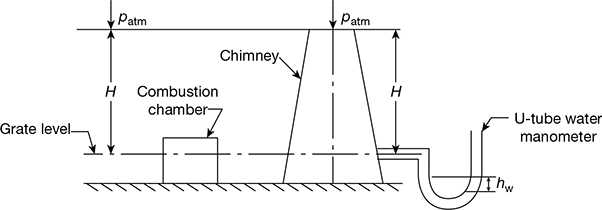
Figure 3.39 Diagrammatic arrangement of natural chimney draught
γg = specific weight of chimney hot gases.
Pressure acting on the grate on the open (atmospheric) side,
p2 = patm + γah
where γa = specific weight of air outside the chimney.
Net pressure difference causing the flow through the combustion chamber, static draught,

Static draught can be measured by a water manometer
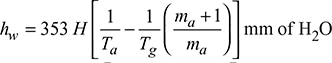
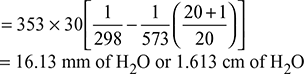
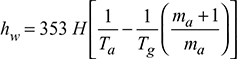
Let hw = difference in water level in the two legs of U-tube manometer, mm
Then ![]()
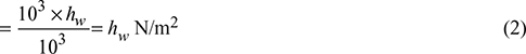
Equating the above two equations, we get
Δp = hw = (γa − γg)H
3 Height and Diameter of Chimney
It can be assumed that the volume of combustion products is equal to the volume of air supplied when both reduced to the same temperature and pressure conditions.
Let ma = mass of air supplied per kg of fuel
Tg = average absolute temperature of chimney gases
Ta = absolute temperature of atmospheric air
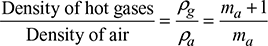
Density of air at atmospheric conditions,
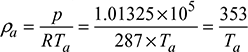
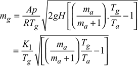
Density of hot gases at temperature, Tg,
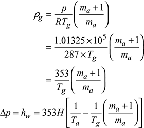
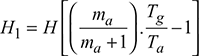
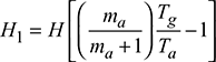
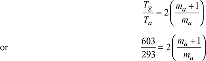
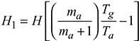
Let Δp be equivalent to H1 metre height of burnt gases.
Then 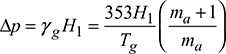
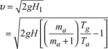
The velocity of gases passing through the chimney is given by,
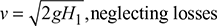
If the pressure loss in the chimney is equivalent to a hot gas column of height h1, then
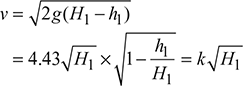
where 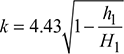
= 0.825 for brick chimney
= 1.1 for steel chimney
Mass of gas flowing through any cross-section of chimney is given by,
mg = Avρg kg/s
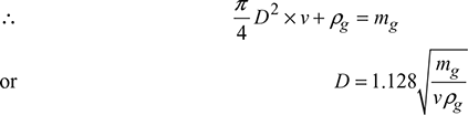
4 Condition for Maximum Discharge Through Chimney
Neglecting losses in chimney,
Density of hot gases, ![]()
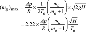
Mass of gases discharged per second, mg = Avρg
where ![]()
The value of mg will be maximum when  , as Ta and ma are fixed.
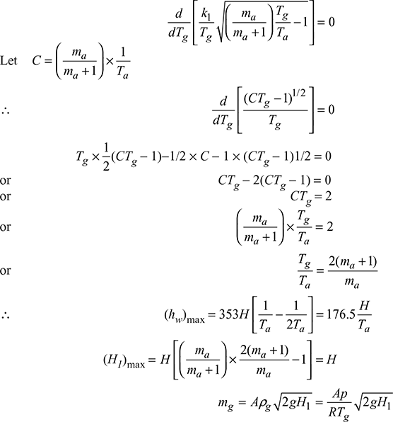
Maximum discharge,
5 Efficiency of Chimney
A certain minimum flue gas temperature is required to produce a given draught with a given height of chimney. Therefore, the temperature of flue gases leaving the chimney in case of natural draught has to be higher than that of flue gases temperature in the case of artificial draught.
Let Tn = absolute temperature of flue gases leaving the chimney to create the draught of hw mm of water.
Tm = absolute temperature of flue gases leaving the chimney in case of artificial draught.
cpg = mean specific heat of flue gases
Extra heat carried away per kg of flue gases due to higher temperature required in natural draught = cpg (Tn − Tm) as Tn > Tm
Draught pressure produced by natural draught system in m of hot gases,
Maximum energy given by H1 to one kg of air at the cost of extra heat
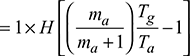
Efficiency of chimney, 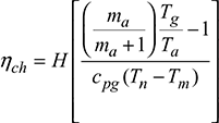
where Tn = Tg
Generally ηch < 1%
6 Advantages and Disadvantages of Natural Draught
Advantages of natural draught are as follows:
- No power is required to produce draught.
- The life of chimney is quite long.
- The chimney does not require much maintenance.
Disadvantages of natural draught are as follows:
- There is very low efficiency.
- It requires a tall chimney (30.48 m minimum).
- Efficiency is dependent on atmospheric temperature.
- There is no flexibility on draught.
7 Draught Losses
The causes of the losses in draught are as follows:
- Frictional resistance offered by the gas passages during flow of gas.
- Loss near the bends in the gas flow circuit.
- Frictional head loss in different equipment, for example, grate, economiser, superheater, etc.
- Heat lost to impact velocity to flue gases.
The total loss is nearly 20% of the total static draught produced by chimney.
8 Artificial Draught
A draught produced by artificial means which is independent of the atmospheric conditions is called artificial draught. It gives greater flexibility to take the fluctuating loads on the plant. The artificial draught may be of mechanical type or of steam jet type. If the draught is produced by a fan, it is called fan (or mechanical) draught, and if it is produced by a steam jet, it is called steam jet draught. Steam jet draught is used for small installations such as locomotives, whereas mechanical draught is invariably used in central power stations.
Forced Draught
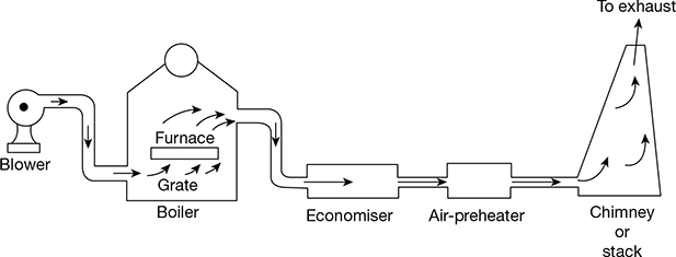
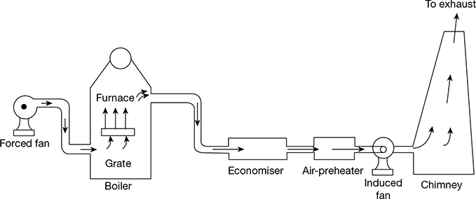
In a forced draught system, a blower is installed near the base of the boiler and air is forced to pass through the furnace, flues, economiser, air-preheater, and to the stack. It is called forced positive draught system because the pressure of air throughout the system is above atmospheric pressure and air is forced to flow through the system. The arrangement of the system is shown in Fig. 3.40. A stack or a chimney is also used to discharge gases high into the atmosphere for better dispersion of ash particles and pollutants.
Induced Draught
In this system, the blower is located near the base of the chimney. The air is sucked into the system by reducing the pressure through the system below the atmospheric pressure. The induced draught fan sucks the gases from the furnace and the pressure inside the furnace is reduced below that of the atmospheric pressure, thus inducing the atmospheric air to flow through the furnace. The draught produced is independent of the temperature of hot gases. Therefore, the gases may be discharged as cold as possible after recovering as much heat as possible in the economiser and the pre-heater. The arrangement of the system is shown in Fig. 3.41.
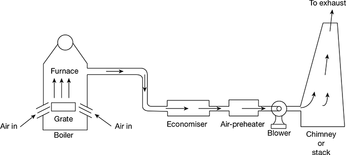
Figure 3.41 Induced draught
9 Comparison of Forced and Induced Draughts
The comparison of forced and induced draughts in given in Table 3.3.
Table 3.3 Comparison of forced and induced draughts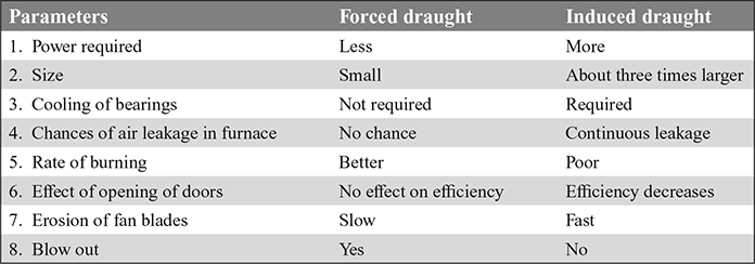
10 Comparison of Mechanical and Natural Draughts
The comparison of mechanical and natural draughts is given in Table 3.4.
Table 3.4 Comparison of mechanical and natural draughts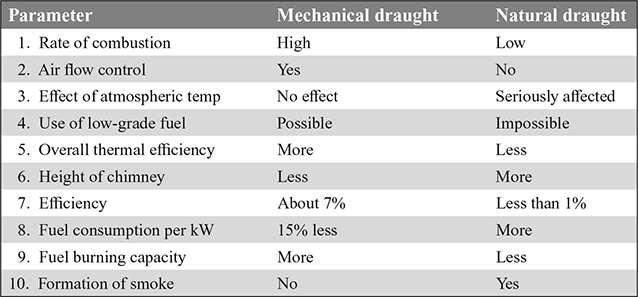
11 Balanced Draught
A balanced draught is a combination of forced and induced draughts. The forced draught overcomes the resistance of the fuel bed and therefore sufficient air is supplied to the fuel bed for proper and complete combustion. The induced draught fan removes the gases from the furnace, maintaining the pressure in the furnace just below atmospheric pressure. This prevents to blow-out of flames and leakage of air inwards, when the furnace doors are opened. The balanced draught is shown in Fig. 3.42.
12 Steam Jet Draught
A steam jet draught of the induced type is shown in Fig. 3.43. A steam nozzle located near the smoke box induces the flow of gases through the tubes, ash pit, grate, and flues. It is generally used for a locomotive boiler.
The steam jet creates pressure below that of the atmosphere in the smoke box. The advantages of steam jet draught are as follows:
- Very simple and economical
- Low-grade fuel can be used
- Forced type system keeps the fire bars cool and prevents the adhering of clinker to them
- Maintenance cost is nil
- Occupies minimum space
However, it cannot be started until high pressure steam is available.
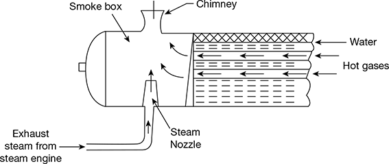
Figure 3.43 Steam jet draught
Example 3.12
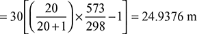
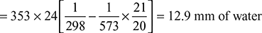
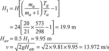
A boiler is equipped with a chimney of 25 m height. The ambient temperature is 27°C. The temperature of flue gases passing through the chimney is 300°C. If the air flow through the combustion chamber is 20 kg per kg of fuel burned, then find the following:
- Theoretical draught in cm of water
- The velocity of flue gases passing through the chimney if 50% of theoretical draught is lost in friction at grate and passage.
Solution
Given that H = 25 m, Ta = 27 + 273 = 300 K, Tg = 300 + 273 = 573 K, ma = 20 kg/kg fuel
 Equivalent gas head,
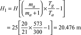
- Available head, Hav = 20.476 × 0.5 = 10.238 mVelocity of flue gases,

Example 3.13
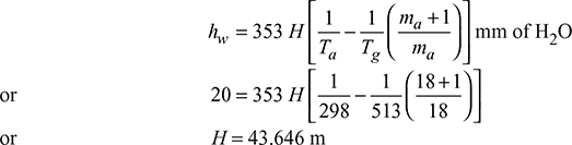
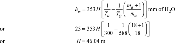
Determine the height of the chimney required to produce a draught equivalent to 2 cm of water if the flue gas temperature is 240°C and ambient temperature is 25°C. The minimum amount of air per kg of fuel is 18 kg.
Solution
Given that hw = 2 cm of water, Tg = 240 + 273 = 513 K, Ta = 25 + 273 = 298 K, ma = 18 kg/kg fuel
Example 3.14
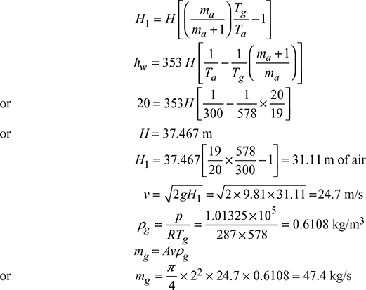
Find the mass of flue gases flowing through the chimney when the draught produced is equal to 2 cm of water. The temperature of flue gases is 305°C and the ambient temperature is 27°C. The flue gases formed per kg of fuel burned are 20 kg. The diameter of the chimney is 2 m. Neglect losses.
Solution
Given that hw = 2 cm, Tg = 305 + 273 = 578 K, Ta = 27 + 273 = 300 K,
1 + ma = 20 kg/kg of fuel.
Example 3.15
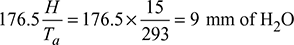
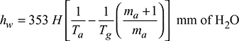
The height of a chimney used in a plant to provide natural draught is 15 m. The ambient air temperature is 20°C. (a) Find the draught in mm of water when the temperature of chimney gases is such that the mass of gases discharged is maximum and (b) if temperature of gases should not exceed 330°C, then find the air supplied per kg of fuel for maximum discharge.
Solution
Given that H = 15 m, Ta = 20 + 273 = 293 K, Tg = 330 + 273 = 603 K
- (hw)max =
- For maximum discharge,
 or 1.029 ma = ma + 1or ma = 34.47 kg/kg of fuel
Example 3.16
A boiler is equipped with a chimney of 30 m height. The ambient temperature is 25°C. The temperature of flue gases passing through chimney is 300°C. If the air flow is 20 kg/kg of fuel burnt, then find (a) draught produced and (b) the velocity of flue gases passing through chimney if 50% of the theoretical draught is lost in friction.
Solution
H = 30 m, Ta = 273 + 25 = 298 K, Tg = 273 + 300 = 573 K, ma = 20 kg, mf = 1 kg
- Draught produced,
- Equivalent gas head,
 Available head, Hav = 0.5 H1 = 12.469 mVelocity of flue gases, v =
Example 3.17
A boiler uses 18 kg of air per kg of fuel. Determine the minimum height of chimney required to produce a draught of 25 mm of water. The mean temperature of chimney gases is 315°C and that of outside air 27°C.
Solution
Given: ma = 18 kg, mf = 1 kg, hw = 25 mm of H2O, Tg = 273 + 315 = 588 K,
Example 3.18
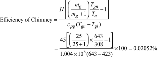
With a chimney of height 45 m, the temperature of flue gases with natural draught was 370°C. The same draught was developed by induced draught fan and the temperature of the flue gases was 150°C. The air flow through the combustion chamber is 25 kg per kg of coal fired. The boiler house temperature is 35°C. Assuming cp = 1.004 kJ/kg K for the flue gases, determine the efficiency of the chimney.
Solution
Given that H = 45 m, Tgn = 273 + 370 = 643 K, Tgi = 273 + 150 = 423 K
mg = 25 kg/kg of coal fired, Ta = 273 + 35 = 308 K, cpg = 1.004 kJ/kgK
Example 3.19
A boiler is provided with a chimney of 24 m height. The ambient temperature is 25°C. The temperature of flue gases passing through the chimney is 300°C. If the air flow through the combustion chamber is 20 kg/kg of fuel burnt, then find (a) the theoretical draught in cm of water and (b) the velocity of flue gases passing through the chimney if 50% of theoretical draught is lost in friction at grate and passage.
Solution
Given that H = 24 m, Ta = 273 + 25 = 298 K, Tg = 273 + 300 = 573 K
ma = 20 kg/kg of fuel burnt,
- Equivalent gas head,
Example 3.20
The following data relate to a boiler using induced draught system:
Length of the duct carrying flue gases = 150 m
Mean size of the square duct = 75 cm2
Mean flue gas velocity in the duct = 900 m/min
Mean temperature of gases passing through duct = 227°C
Plenum pressure = 15 cm of water
Atmospheric pressure = 75 cm of Hg
Number of 90° bends = 4
Number of 45° bends = 4
Loss of draft in every 90° bend = 0.1 cm of water
Draft available from chimney = 1.5 cm of water
Fuel bed resistance for under fired stoker = 10 cm of water
Fan efficiency = 60%
Motor efficiency driving fan = 92.5%
Characteristic gas constant for gases = 0.294 kJ/kgK
Friction factor, f, corresponding to round section duct = 0.006
Assuming that a 45° bend equal one-half of 90° bend and that the resistance offered by square duct is 20 % greater than a similar round duct, determine the following:
- Draft to be produced due to friction in square cross-section duct in mm of water
- Draft due to velocity head of flue gases in mm of water
- Total draft for the boiler
- Draft to be produced by induced fan
- Power required to drive fan[IES, 2011]
Solution
Given that L = 150 m, f = 0.006, As = 75 cm2, vg = 900 m/min, C = 1.2, Δp = 15 cm of water, tg = 227°C, patm = 75 cm of Hg, ηf = 0.6, ηm = 0.925, Rg = 0.294 kJ/kgK
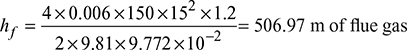
- Frictional head loss in duct carrying flue gases,
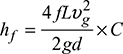 Equivalent diameter of round duct,
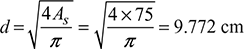
 Chimney draft produced, pc = 15 mm of water or 15 × 9.81 = 147.15 N/m2Atmospheric pressure,
 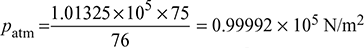 Pressure of hot flue gases, pg = patm − pc = 0.9992 × 10⁵ − 147.15= 99,844.6 N/m2Density of hot flue gases,
 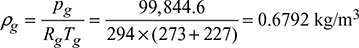 Frictional head loss in square duct in terms of mm of water
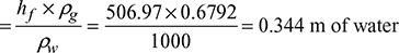 = 344 mm of waterPlenum pressure drop in duct = 150 mm of waterDraft to be produced due to friction in duct = 344 + 150 = 494 mm of water
 - Draft due to velocity head of flue gases:4 bends of 90° =
 4 bends of 45° = 0.5 × 41.28 = 20.64 m of hot flue gasesTotal draft due to velocity head = 41.28 + 20.64 = 61.92 m of hot flue gases
 Loss of draft due to 90° bends = 4 × 1 = 4 mm of waterLoss of draft due to 45° bends = 2 mm of water
 - Fuel bed resistance for under fired stoker = 100 mm of waterTotal draft for the boiler = 344 + 150 + 42 + 4 + 2 = 542 mm of water
- Draft to be produced by induced fan, h = 542 + 100 = 642 mm of H2O
- Volume flow rate of flue gases through the duct, V̇ = As × vg= 75 ×10−4 × 15 = 0.1125 m3/sPower required to drive fan =
Example 3.21
In a steam power plant, the steam generator generates steam at the rate of 120 t/h at a pressure of 100 bar and temperature of 500°C. The calorific value of fuel used by steam generator is 41 MJ/kg with an overall efficiency of 85 %. In order to have efficient combustion, 17 kg of air per kg of fuel is used for which a draught of 25 mm of water gauge is required at the base of stack. The flue gases leave the steam generator at 240°C. The average temperature of gases in the stack may be taken as 200°C and the atmospheric temperature is 30°C. Determine (i) the height of stack required, and (ii) the diameter of stack at its base. Take the following steam properties for solution: h = 3375 kJ/kg, hf = 632.2 kJ/kg.
Solution
Given that ms = 120 t/h, p = 100 bar, t = 500°C, CV = 41 MJ/kg, ηoverall = 85%, m = A/F = 17 kg/kg of fuel, hw = 25 mm, tg = 240°C, tgs = 200°C, tatm = 30°C, h = 3375 kJ/kg, hf = 632.2 kJ/kg
 Density of flue gases,
 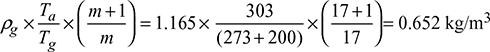 Δp = 103 × ghw × 10−3 = gH (ρa − ρg)25 = H(1.165 − 0.652)Height of stack, H = 48.73 m
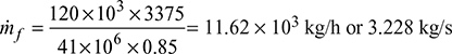 Mass of air, ṁa = 17 × ṁf = 54.878 kg/sMass of flue gases, mg = ṁf + ṁa = 3.228 + 54.878 = 58.106 kg/s
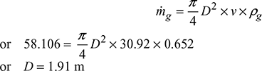
Leave a Reply