These are the appliances installed to increase the overall efficiency of the steam power plant. The various accessories installed are pressure reducing valve, steam trap, steam separator, economiser, air preheater, superheater, feed pump, and injector.
The functions of the various accessories are as follows:
- A pressure reducing valve maintains constant pressure on its delivery side with fluctuating boiler pressure.
- The function of steam trap is to drain of water resulting from the partial condensation of steam from steam pipes and jackets without allowing steam to escape through it.
- The function of the steam separator is to separate suspended water particles carried by steam on its way from the boiler to the prime mover.
- The function of an economiser is to recover some of the heat carried away in the flue gases up the chimney and utilise for heating the feed water to the boiler.
- An air preheater recovers some portion of the waste heat of the flue gases by preheating the air supplied to the combustion chamber.
- Superheaters are used to increase the temperature of steam above its saturation temperature.
- The function of a feed pump is to pump water to the water space of the boiler.
- The function of an injector is to feed water to the boiler with the help of a steam jet.
We shall discuss the air preheater, economiser, and superheater in detail.
1 Air Preheater
In the air preheater, air is heated by the heat carried away by the flue gases and goes as a waste through the chimney. It is situated between the economiser and the chimney. Air preheaters are of three types—tubular, plate type, and regenerative.
In the tubular type of air preheater, shown in Fig. 3.29, the air passes down outside the tubes and the flue gases through the tubes before going to the induced draught fan at the base of the chimney. Baffles are provided across the tubes to make the air follow a zigzag path a number of times to utilise more heat of flue gases.
In the plate type of air preheater, there are alternate chambers provided by the plate surfaces for the flow of flue gases upwards to the induced draught fan and for the flow of combustion air down of combustion air downwards.
In the regenerative type, the air preheater chamber is divided into two rotating compartments. The heating surfaces are made up of a series of corrugated sheets between which the hot flue gases pass upwards on one side and the combustion air passes down on the other side. Due to the rotation of pre-heater at a very low speed, the heater surface comes in contact with combustion air and the cooled surface is again heated by the flue gases. This alternate heating and cooling of heating surface is called regenerative heating and is more effective than other types.
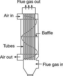
Figure 3.29 Tubular air preheater
2 Economiser
The Green’s economiser shown in Fig. 3.30 is used for boilers of a medium pressure range up to about 25 bar. It consists of groups of vertical cast iron pipes fitted at their two ends to cast iron boxes, at the top and bottom. All the tubes are enclosed within the brick work of the economiser. There are two pipes, C and D, outside the brick work E. Rows of top and bottom boxes are connected to these top and bottom pipes. The feed water is pumped to the bottom pipe D. From here, it goes to the bottom boxes and rise up in the groups of vertical pipes into the top boxes. From the top boxes, it goes to the pipe C from where it passes to the water space of the boiler through the check valve. F is a stop valve for entry and G is a stop valve for exit of the water from the economiser. S is a safety valve. These tubes are continuously scraped by scrapers J to remove soot collected on them due to the passage of flue gases through the economiser. A pair of scrapers is connected by a chain passing over a pulley such that one scraper comes down and the other attached to the same chain goes up. L is the soot chamber where soot is collected and removed through a soot door.
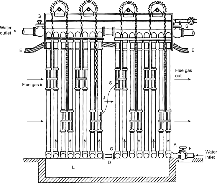
Figure 3.30 Economiser
3 Superheater
The superheater commonly used in a Lancashire boiler is shown in Fig. 3.30. It consists of two headers and a set of superheater tubes made of high-quality steel in the form of U-tube. It is located in the path of furnace gases just before the gases enter the bottom flue. The amount of hot gases passed over the superheater tubes should be in proportion to the amount of superheated steam passing through the tubes. Otherwise, the tubes would be over heated. To avoid this, the hot gases are diverted as shown in Fig. 3.31. The superheater is put out of action by turning the damper upward to the vertical position. In this position of the damper, the gases coming out from the central flue pass directly into the bottom flue without passing over the superheater tubes.
For getting superheated steam, the valves A and B are opened and valve C is closed. The damper is kept open as per the quantity of steam flowing through the pipe. For this position, the flow direction of steam is shown in Fig. 3.31. If wet steam is required, valves A and B and the gas damper are kept closed, and valve C is kept open. In this case, steam comes directly from the boiler through valve C. By adjusting the gas damper, the temperature of steam coming out of superheater is always maintained constant, irrespective of the amount of steam passing through the superheater.
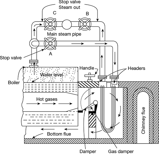
Figure 3.31 Superheater
Leave a Reply