Different fittings and devices necessary for the operation and safety of a boiler are called boiler mountings. The various boiler mountings are as follows:
- Water- level indicator
- Pressure gauge
- Steam stop valve
- Feed check valve
- Blow-down cock
- Fusible plug
- Safety valve: spring loaded, dead weight, lever type
- High steam and low water safety valve.
1 Water Level Indicator
The water-level indicator indicates the level of water in the boiler constantly. Every boiler is normally fitted with two water-level indicators at its front end. Figure 3.19 shows a water-level indicator used in low pressure boilers. It consists of three cocks and a glass tube. The steam cock D keeps the glass tube in connection with the steam space and cock E puts the glass tube in connection with the water space in the boiler. The drain cock K is used to drain out the water from the glass tube at intervals to ascertain that the steam and water cocks are clear in operation. The glass is generally protected with a shield.
For the observation of water level in the boiler, the steam and water cocks are opened and the drain cock is closed. The rectangular passage at the ends of the glass tube contains two balls. If the glass tube is broken, the balls are carried along its passage to the ends of the glass tube and flow of water and steam out of the boiler is prevented.
2 Pressure Gauge
The pressure gauge is used to indicate the steam pressure of the boiler. The gauge is normally mounted in the front top of the steam drum. The commonly used pressure gauge is the Bourdon type pressure gauge shown in Fig. 3.20. It consists of an elastic metallic tube of elliptical cross-section bent in the form of circular arc. One end of the tube is fixed and connected to the steam of the boiler and the other end is connected to a sector wheel through a link. The sector remains in mesh with a pinion fixed on a spindle. A pointer is attached to the spindle to read the pressure on a dial gauge.
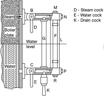
Figure 3.19 Water-level indicator
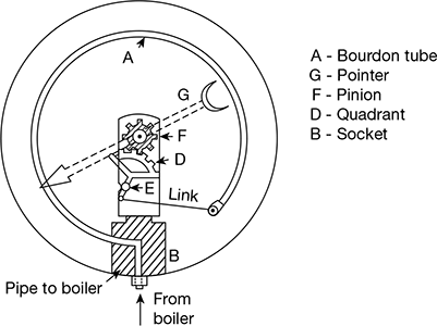
Figure 3.20 Pressure gauge
When high pressure steam enters the elliptical tube, the tube section tends to become circular, which causes the other end of the tube to move outward. The movement of the closed end of the tube is transmitted and magnified by the link and sector. The sector is hinged at a point on the link. The magnitude of the movement is indicated by the pointer on the dial.
3 Steam Stop Valve
The function of the stop valve is to regulate the flow of steam from the boiler to the prime mover as per requirement and shut off the steam flow when not required.
A commonly used steam stop valve is shown in Figure 3.21. It consists of a main body, valve, valve seat, nut, and spindle, which pass through a gland to prevent leakage of steam. The spindle is rotated by means of a hand wheel to close or open.
4 Feed Check Valve
The function of the feed check valve is to allow the supply of water to the boiler at high pressure continuously and to prevent the back flow of water from the boiler when the pump pressure is less than boiler pressure or when the pump fails.
A commonly used feed check valve is shown in Fig. 3.22. It is fitted to the shell slightly below the normal water level of the boiler. The lift of the non-return valve is regulated by the end position of the spindle which is attached to the hand wheel. The spindle can be moved up or down with the help of hand wheel which is screwed to the spindle by a nut. Under normal conditions, the non-return valve is lifted due to the water pressure from the pump and water is fed to the boiler. If the case pump pressure falls below boiler pressure, the valve is closed automatically.
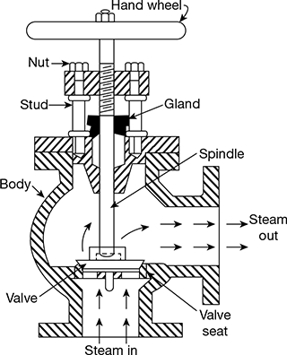
Figure 3.21 Steam stop valve
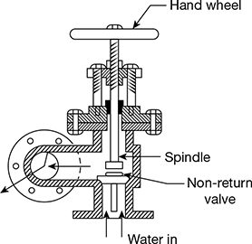
Figure 3.22 Feed check valve
5 Blow-Down Cock
The function of the blow-down cock is to remove sludge or sediments collected at the bottommost point in the water space in a boiler, while the boiler is steaming. It is also used for complete draining of the boiler for maintenance.
A commonly used type of blow-down cock is shown in Fig. 3.23. It consists of a conical plug fitted accurately into a similar casing. The plug has a rectangular opening which may be brought into the line of the passage of the casing by rotating the plug. This causes the water to be discharged from the boiler. The discharge of water may be stopped by rotating the plug again. The blow-down cock should be opened when the boiler is in operation for quick forcing out of sediments.
3.11.6 Fusible Plug
The main function of the fusible plug is to put off the fire in the furnace of the boiler when the water level in the boiler falls below an unsafe level and thus avoid the explosion which may occur due to overheating of the tubes and shell. The plug is generally fitted over the crown of the furnace or over the combustion chamber.
A commonly used fusible plug is shown in Fig. 3.24. It consists of a hollow gun metal body screwed into the fire box crown. The body has a hexagonal flange to tighten it into the shell. A gun metal plug is screwed into the gun metal body by tightening the hexagonal flange formed into it. There is yet another solid plug made of copper with conical top and rounded bottom. The fusible metal holds this conical copper plug and the gun metal plug together due to depressions provided at the mating surfaces.
During normal operation, the fusible plug remains submerged in water and on no account, its temperature can be more than the saturation temperature of water.
The fusible metal is protected from direct contact with water or furnace gases. When the water level in the boiler shell falls below the top of the plug, the fusible metal melts due to overheating. Thus, the copper plug drops down and is held within the gun-metal body by the ribs. The steam space gets communicated to the fire box and extinguishes the fire. The fusible plug can be put into position again by interposing the fusible metal.
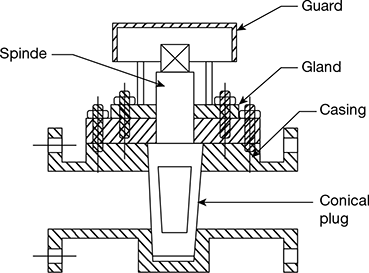
Figure 3.23 Blow-down cock
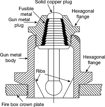
Figure 3.24 Fusible plug
7 Safety Valves
The function of a safety valve is to prevent the steam pressure in the boiler exceeding the desired rated pressure by automatically opening and discharging steam to atmosphere till the pressure falls back to normal rated value. There are three types of safety valves—spring loaded (Ramsbottom) type, dead weight type, and lever type.
- Spring-loaded safety valve: The spring-loaded safety valve of the Ramsbottom type is shown in Fig. 3.25. The spring holds the two valves on their seats by pulling the lever down. The lever is provided with two conical pivots, one integrally forged with the lever and the other pin connected to one end. The upper end of the spring is hooked to the lever midway between the two pivots. The lower end is hooked to the shackle fixed to the valve chest by studs and nuts. The shackle and the lever are also connected by two links, one end of which is pin-jointed and the other end has a slot cut into it to allow for the pin to slide in it vertically, thus allowing the lever to be lifted and retaining the link connection. These links are provided as a safety measure in case the spring breaks, the lever should not fly off. The lever projects on one side for manual operation to check the satisfactory working of the device.
- Dead weight safety valve: In this type of device, as shown in Fig. 3.26, the steam pressure in the upward direction is balanced by the downward force of dead weights acting on the valve. It is generally used on low capacity boilers like the Lancashire boiler. The bottom flange is directly connected to seating block on the boiler shell.
- Lever safety valve: A typical lever safety valve is shown in Fig. 3.27. The lever is the second kind with effort in the middle of fulcrum and load. It is suitable for stationary boilers.
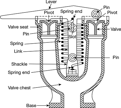
Figure 3.25 Spring loaded safety valve
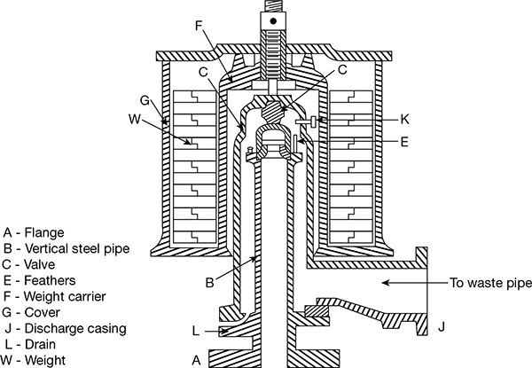
Figure 3.26 Dead weight safety valve
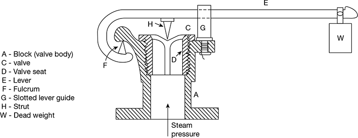
Figure 3.27 Lever safety valve
8 High Steam and Low Water Safety Valve
The functions of water safety valve are of two, namely to blow out if the steam pressure is higher than the working pressure and to blow out steam when the water level in the boiler is low. It is perhaps the most important mounting on the boiler. Figure 3.28 shows the details of Hopkinson’s high steam and low water safety valve.
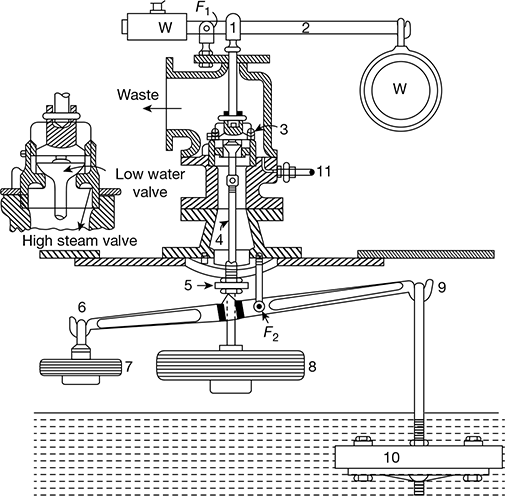
Figure 3.28 High steam and low water safety valve
F1 is the fulcrum, W the weight suspended on one end of the lever, and W is the adjustable balance weight on the other end, which can be fixed in position on the lever 2 by a set screw. A predetermined force is exerted through the strut 1 on the outer valve.
The arrangement of the inner valve with spindle 4 and a dead weight 8 acts as dead weight safety valve. However, the load on the outer valve is both due to dead weight and strut thrust. If the pressure in the boiler exceeds the limit, the valve lifts and the steam escapes to waste.
On one end 9, of lever 6−9 with fulcrum F2, is attached a float 10 and on the other end is fixed a balance weight 7. When the float 10 is submerged in water, the lever is balanced about fulcrum F2. As soon as the float is uncovered, it gets unbalanced and tilts the lever to the right. This lever has a projecting knife edge which is clear of the collar 5 when the float is submerged. As soon as it tilts towards right, it establishes contact with the collar and pushes the spindle 4 up, thus raising the inner valve from its seat. Thus steam starts escaping out through the waste pipe. A drain connection 11 is provided to drain off the condensed steam.
Leave a Reply