Structures such as buildings immersed in a moving fluid experience fluid loading forces. These forces are caused by several physical phenomena. The phenomena may be divided into three main categories: (i) steady incoming flow that impinges on the structure, (ii) unsteady incoming flow, and (iii) eddies (vortices) that form in the fluctuating wake flowing past the structure. The manner in which a structure responds to the flow forces is governed by several factors, the most important being: (i) its geometrical shape and dimensions; (ii) its boundary conditions and rigidity (stiffness) and mass distributions, which govern its fundamental and higher natural frequencies; and (iii) its vibration damping [137].
The structures may be divided into two main types: (i) stiff structures that are relatively rigid and that have fundamental bending and torsional frequencies that are above the predominant fluctuation frequencies in the incoming flow and wake eddy formation rates and (ii) flexible structures that have fundamental frequencies much lower than or that coincide with the frequencies of the fluctuating forces in the incoming flow and/or wakes from any neighboring structures upstream [137].
Dynamic forces experienced by “rigid” structures can be divided into two main types: (i) longitudinal forces in the flow direction mostly caused by unsteady incoming flow and (ii) lateral and torsional forces that are mainly caused by the vortex shedding in the structure’s own wake. Flexible structures can experience additional forces caused by motion of the structure itself in response to the flow forces. Motion of the structure, sometimes caused by aeroelastic effects, can alter the flow and result in self‐generating feedback mechanisms known such as galloping, flutter, or vortex‐generated motion resulting in increased vortex shedding. In addition, aeroelastic effects associated with vortex shedding are also important since, when the vortex shedding frequency coincides with a natural frequency, feedback motion results in which the vortex‐generated motion intensifies the vortex shedding.
There is a considerable body of literature describing the vibration of structures caused by fluid flow. Crocker [137] has described the response of structures to fluid flow forces and in particular the response of buildings, towers, and other structures to forces caused by wind. There are many books covering the dynamic response of structures that are also useful in study of this topic [138].
The wind flow speed and direction normally continually change. The wind in most cases is highly turbulent, and its characteristics depend on a number of factors, the most important being: (i) the surface roughness of the terrain (which differs according to whether the surface is water, open terrain, suburban, or urban) and (ii) the height above the ground [139–143].
Wind speeds and profiles are typically referenced with respect to a standard height of 10 m (33 ft) above ground level. See Figure 12.55. It can maintain a fairly steady direction, but it can also change in speed and in direction (known as veering). When an obstruction such as a building is encountered, the flow pattern changes markedly. (see, e.g. Figure 12.56) Buildings introduce distinct individual wind flow patterns. Near large buildings the wind can behave in a very complicated manner due to local flow accelerations, formation of eddies, and flow reversals. For example, winds can reverse direction and head downward in the “upwind roller” that can form in front of a large tall building. The wind can also roll and flow upward behind such a building (see Figure 12.57).
By watching the behavior of vegetation, birds in flight, flags flying, and the like near a building, it is possible to observe such wind flow patterns in real life. The use of scale‐model buildings in wind tunnels makes it possible to reveal such wind flows by the use of flow visualization techniques (e.g. smoke). Wool or cotton tufts attached to the model building and ground surfaces are also used sometimes for flow visualization.
Wind velocities vary widely in different parts of the world. For example, in England and Wales, large cities and towns rarely experience wind gusts that exceed 110 km/h (stagnation pressure p = 560 Pa) (70 mph). Coastal areas can have gusts of up to 145 km/h (stagnation pressure p = 970 Pa) (90 mph). Some areas in the north of England and Scotland can be subjected to gusts that exceed 160 km/h (p = 1185 Pa) (100 mph.)
12.9.4.1 Wind Excitation of Buildings
The wind excitation forces on building structures may be divided into two main categories: (i) fluctuating forces in the wind direction on the structures caused by the turbulent pressure fluctuations that exist in the approaching wind flow and (ii) fluctuating forces caused by turbulent eddies shed in the wake of the structure. These eddies (vortices) shed in the structure’s wake mostly result in fluctuating forces in the cross‐wind direction and to a lesser extent in the torsional direction. Wind excitation forces and the building vibrations they cause may be further subdivided and are now described in more detail in the following sections in this chapter [138–147].
As discussed already, the response of a building structure to wind depends not only on the wind characteristics but on the structural parameters as well. Very stiff structures deflect little in the wind, and their response can be treated as simple random forced response problems. However, flexible structures such as road signs, tall bridges, tall buildings, communication towers, and the like can respond appreciably and their movement can change the flow. The interaction of the structural motion and flow is known as an aeroelastic phenomenon. The calculation of the aeroelastic response of building structures is much more complicated than that of a pure forced response problem. Although many attempts have been made to calculate the response of rigid and flexible building structures to wind, many unknowns and variables in the wind flow, speed and direction with time, height above the ground, interactions with other structures, and complicated building geometries make calculations difficult [139–144, 146, 147]. In most cases, scale models need to be tested in wind tunnels to obtain reliable results. Figure 12.58 shows a schematic of wind effects and building excitation effects.
12.9.4.2 Structural Vibration Response of Buildings and Towers
Figure 12.59 presents a schematic that indicates the vibration amplitude responses of a building structure to the different types of excitation as classified in Figure 12.58.
a) Types of Building Vibrations
As already discussed in Section 12.12.1 of this chapter, fluid flow and wind forces are responsible for a variety of vibratory mechanisms in structures. In the case of inline buffeting, (Figure 12.59a), the vibration amplitudes generated increase nonlinearly and very rapidly with flow speed. This is because motion can be regarded as forced motion, and the turbulent flow forces involved are proportional to flow velocity squared. It is important to know the fundamental natural frequency of a structure if it is in forced motion since below the natural frequency the response is mostly stiffness‐controlled, at or near to the natural frequency it is damping‐controlled, and above the natural frequency it is mass (or inertia) controlled. In cross‐wind vortex shedding motion (see Figure 12.59b), again a knowledge of the structural fundamental natural frequency is needed since by careful building design, it may be possible to modify this frequency and change it so that it only becomes a problem at low wind speed at which excitation forces are minimal.
In cases of aerodynamic instability (galloping or flutter) such instabilities only begin at a critical wind speed (see Figure 12.59c), and again the natural frequencies of the structure are involved in the vibration as described before in this chapter.
b) Natural Frequencies of Building Structures
The natural frequencies of a building can be calculated from knowledge of its stiffness and mass distributions with a numerical program such as the FEM. Figure 12.60 shows a schematic distribution of the mass and stiffness distributions of a 210‐m telecommunications tower [144]. The first three natural frequencies and mode shapes of vibration of the tower are shown in Figure 12.60. These are seen to be very low, the first two being less than 1 Hz. Often vibration in the fundamental natural frequency is dominant and most important. Although FEM programs can be used to calculate the fundamental natural frequency, it has been found that the calculation is no more accurate than using an empirical calculation based on the height of the building alone and use of an approximate formula such as Eq. (12.84) [144, 148]
(12.84)![]()
where h is the building height in metres.
The reason that the fundamental natural frequency is dominated by the building height appears to be that as the buildings grow taller they become more massive, and then stiffer supports must correspondingly be used to support the building’s weight. Figure 12.61 shows measured experimental data for building height plotted against fundamental natural frequencies of a large number of tall buildings. Equation (12.84) is also plotted in Figure 12.61. It is seen that this equation is a good fit to most of the experimental data. The fundamental natural frequency of a building is of considerable importance, but so are several other building properties. Since there is a continuing trend to construct building structures of increasing height, wind‐induced vibration of tall structures is a topic of increasing concern for structural engineers.
The three most important properties of structures that are relevant to wind‐induced vibration are: (i) shape, (ii) stiffness (or flexibility), (ii) fundamental natural frequency, and (iv) damping [144].
12.9.4.3 Methods of Building Structure Vibration Reduction and Control
When structures are excited into motion, the forces opposing the motion are due to inertia, stiffness, and damping. It is impractical to increase the mass of the building. Increasing the stiffness of a building can, in principle, reduce its deflection to wind forces, although often there is a limit to the amount of stiffness increase that can be achieved. However, useful increases in stiffness can be achieved relatively easily in the case of masts, antennas in some cases by the use of guy wires and cables. The dynamics of guyed masts are complicated because tensioning of the guy cables is applied and the vibrations of the guy–mast system tend to be nonlinear in character. The guy cables themselves normally vibrate, resulting in some useful damping [144]. Various types of structural damping are illustrated in Figure 12.62.
For wake buffeting, across‐wind vortex‐induced vibration, galloping, and flutter, damping forces become dominant in controlling vibration. Passive damping can be applied successfully in such cases. Different passive damping elements have been used in practice, and several new designs have been proposed. The World Trade Center in New York had about 10 000 passive “friction” dampers mounted in the truss structures (see Figure 12.63). Tuned vibration dampers (TMD) are also now used in many tall buildings. The first tall building to have such a device was the 280‐m high Citicorp Center in New York City [144]. This employed a 270 000‐kg concrete block “floated” on a hydrostatic support system. Springs are attached to the mass and tuned to give the TMD system a natural frequency the same as the fundamental vibration frequency of the building. In addition, hydraulic dampers are applied to dissipate the vibration energy. Stops must be provided to prevent excessive damaging motion of the floating mass during intense storms. A problem is that electrical power is needed to provide hydrostatic pressure for the oil suspension system. If the electrical power fails during a storm, then the TMD system becomes inoperative.
The principle of operation of the tuned mass damper is that as the building vibrates at its natural frequency, the tuned damper will also vibrate at the same frequency, but out of phase and thus applying forces opposing the motion of the building.
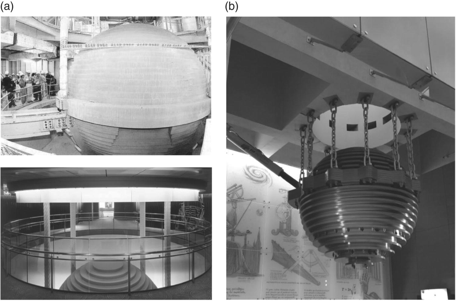
More recently, tall buildings have used TMDs made of large masses suspended by cables, rather like pendulums. The 500‐m building in Taiwan opened in November 2004 has a 500 000‐kg mass suspended on four cables near the top of the building between the 86th and 89th floors (see Figure 12.64). As the building vibrates, the mass swings in an opposite direction, and pneumatic dampers are used to dissipate vibration energy. Excessive damaging vibration is prevented by the dampers. The system is mainly designed to reduce wind‐induced vibrations by 35%, but it is said to also suppress earthquake vibrations. Since the building is situated only 1 km from a fault line, earthquake damage is of concern. During construction in 2003, a 6.8‐scale earthquake was experienced. The building survived the earthquake and the tuned mass system is said to have worked satisfactorily, although a construction crane fell from the 50th floor during the earthquake killing five construction workers. Another example of a tuned‐pendulum mass damper is shown in Figure 12.64b. This 3.5‐m diameter steel sphere is installed near the top of an 83‐m building in Santiago, Chile, and designed to reduce the amplitude of vibration during an earthquake. The 150 000‐kg mass is suspended on 12 independent chains with two dampers to dissipate vibration energy.
Other types of damping systems have been proposed and, in some cases, implemented. Some such dampers rely on liquid motion inside rigid containers to absorb and dissipate the vibration energy. For example, nutation dampers have been investigated by Modi and Welf [149]. Tuned liquid dampers (TLD) and tuned liquid column dampers (TLCD) have been investigated for use in buildings by Sakai et al. [150] and Xu et al. [151]. These dampers have been used successfully in spacecraft satellites and marine vessels by Amieux and Dureigne [152]. TLD and TLCD systems have some advantages over TMDs, including lower costs, less maintenance, and easier construction and handling [151].
12.9.4.4 Human Response to Vibration and Acceptability Criteria
In most cases, building vibration caused by wind is insufficient to cause structural damage, except in some cases to the superstructure or cladding (see Figure 12.65). The vibration is, however, often unpleasant and worrying for occupants. The swaying of tall buildings particularly at the tops can be disconcerting for occupants to say the least. Most studies on acceptability of vibration have been for frequencies higher than those normally encountered in tall buildings. Some studies have been conducted with very low frequency vibration using vibration simulators. Other results have been obtained from extrapolations from high frequency to low frequency to arrive at criteria for acceptability of vibration at very low frequencies less than 1 Hz. Most subjects report that they cannot sense vibration with acceleration less than about 0.01 g. If the vibration has an acceleration exceeding about 0.1 g, most subjects find the vibration is becoming intolerable. Table 12.6 lists some human acceptability criteria. Additional criteria for human comfort and annoyance for vibration in buildings are discussed in Chapter 6.
Table 12.6 Human acceleration acceptability criteria.
Source: From Refs. [139, 144, 153].
| Perception | Acceleration Limits |
|---|---|
| Imperceptible | a < 0.005 g |
| Perceptible | 0.005 g < a < 0.015 g |
| Annoying | 0.015 g < a < 0.05 g |
| Very annoying | 0.05 g < a < 0.15 g |
| Intolerable | a > 0.15 g |
Another source of vibration in buildings is earthquakes. Protection of buildings from seismic‐induced vibration is extremely important and this subject has been included in several national and IBCs (e.g. see Chapter 16 of Ref. [110]). Evidently, concerns with building response to earthquakes depend upon the use of the building, the geographical location of the building and the geological characteristics of the soil. Building codes to protect buildings from vibrations caused by seismic excitation have been developed in earthquake‐prone regions, such as Chile, Greece, and California in the U.S. These codes are mostly aimed to preserve the structural integrity of buildings and prevent their collapse during major earthquakes rather than avoid unpleasantness to occupants. Seismic design of buildings and design approaches of seismic isolators are beyond the scope of this book, but a thorough overview of these approaches is provided in Ref. [154] with support of extensive references.
Leave a Reply