There are several reasons for making sound transmission measurements, including: (i) to make tests under standardized laboratory conditions which should give repeatable comparisons of the performance of different partition structures and materials, (ii) to conduct laboratory tests in development work on partitions to indicate changes in sound TL which are caused by small design changes, (iii) to decide from field tests if design goals or commercial bids have been met, and (iv) to determine from field tests if criteria have been met on NR between two locations in a building. There are a number of methods which have been devised for the measurement of TL. The most widely used laboratory method consists of the use of a transmission suite. However, there are several other methods which are occasionally used in the laboratory or “in the field.” It should be noted that the transmission suite method cannot be used exactly “in the field” since the sound fields are rarely sufficiently diffuse. However, provided the practical difficulties are understood, the transmission suite method can be adapted for field use.
12.7.1 Laboratory Methods of Measuring Transmission Loss
a) Transmission Suite Method
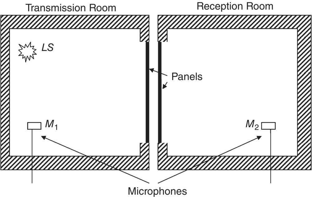
This method consists of the use of two reverberant rooms which are separated by the panel under investigation. Reverberant rooms are used so the sound falling on the panel has equal probability of approaching from any direction (random incidence sound). The rooms are vibration‐isolated from each other, by mounting them on vibration isolators, in order to minimize mechanical “flanking” transmission between the rooms. The panel under test is normally attached to one of the rooms if it is a single panel. If it is a double panel, one leaf is normally attached to one room and the other leaf to the other room, unless the additional effect of flanking transmission within the double panel is being considered. A typical transmission suite is shown schematically in Figure 12.42. Procedures for use of a sound transmission suite have been standardized so that results with different partition structures or materials should be comparable even though they were obtained in different laboratories.
The ISO has published ISO 10140‐2 [67]. The American Society for Testing Materials (ASTM) has also produced an elaborate standard test method E90‐09 [68]. These standards are similar and on agreement on the procedures to be followed in laboratory tests. Unfortunately, in the case of “field” tests, the situation is less satisfactory, since measurement conditions in the field are never ideal, the results are dependent upon the particular installation and building, and the results can be difficult to interpret.
In the reverberant room or transmission suite method, the walls of the two rooms are made as acoustically “hard” as possible, by keeping absorbing material to a minimum in order to keep the acoustic fields in each room reverberant and diffuse. A steady sound is made in the first room, known as the transmission room, by means of a loudspeaker (LS). The sound pressure level is measured in the first room and also in the second room, known as the reception room, with the two microphones M1 and M2. The microphones M1 and M2 are moved to randomly selected positions in the two rooms and the measurements repeated. Alternatively, the microphones are continuously moved in each room. Thus, space‐average values of the sound pressure levels (Lp1 and Lp2) are determined from one of these methods. This procedure is repeated using sound at several different frequencies. It is normal practice to use one‐third octave bands of white noise at each frequency, although sometimes warble tones are used instead.
The noise reduction, NR of the panel is given by
(12.66)![]()
Note that NR = Lp1 − Lp2 = 10 log ε1/ε2 since the energy density ε is p2rms/ρc2 in a sound field (see Eq. (3.70)). However, this does not represent exactly the transmission loss TL of the panel since the NR is dependent upon the acoustic absorption in the receiving room. The acoustic absorption in the receiving room can be determined by producing a sound in the room and measuring the reverberation time (TR2) when the sound is cut off (see Section 3.14.3 of this book).
The TL can be deduced from the previously described measurements as follows. It is assumed that there is no flanking transmission and that all the energy transmitted from the transmission room to the receiving room takes place through the panel. It is also assumed that the acoustic absorption is small enough and the measurements made at a frequency, which is high enough for the sound fields in each room to be reverberant and diffuse.
When a steady state is reached, the sound energy densities in transmission room 1 and receiving room 2 are ε1 and ε2, and it may be shown [38] that the power flow through the panel ![]() is
is
(12.67)![]()
where S is the panel area and the transmission coefficient, τ, is the fraction of incident energy transmitted (see, for example, Eq. (12.10)). In the steady state,
(12.68)![]()
where ![]() is the power dissipated in the receiving room due to absorption and
is the power dissipated in the receiving room due to absorption and ![]() is the power retransmitted back to the transmission room from the receiving room. Thus,
is the power retransmitted back to the transmission room from the receiving room. Thus,
(12.69)![]()
where A is the effective absorption area of the receiving room. Thus,
(12.70)
(12.71)
and
(12.72)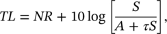
where NR is the noise reduction.
As already described, ε1 and ε2 may be determined from measurements of the space‐averaged sound pressure levels in rooms 1 and 2 made with the microphones M1 and M2. The area of the panel may also be determined. However, the effective absorption of the receiving room must be determined by decay measurements in the receiving room.
This is normally determined at each one‐third octave band center frequency. White noise is produced in the receiving room by supplying a one‐third octave band of white noise to a loudspeaker. The supply is terminated, and the time for the sound pressure level Lp2 to decay 60 dB is determined.
The rate of energy decay in the receiving room is given by
(12.73)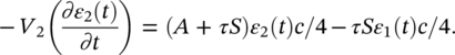
However, unless a panel is very lightweight and τ is large, τSε1(t)c/4 is normally neglected. With this term neglected, Eq. (12.56) is satisfied by the exponential law:
(12.74)![]()
where β is the energy decay constant given by
(12.75)![]()
and ε0 is the energy density when the acoustical source is terminated.
The reverberation time TR2 is given (from Eq. (12.74)) by
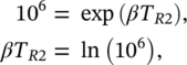
and, substituting for β from Eq. (12.75),
(12.76)![]()
From Eq. (12.72)
(12.77)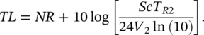
Equation (12.77) is the result which must be used to correct the measured NR of a panel (or apparent transmission loss) to obtain the TL. Equation (12.77) may also be obtained using SEA (see Eq. (12.58a)). Now, substituting the Sabine equation (see Section 3.14.3 of this book) TR2 = 0.161 V/A into Eq. (12.77) we obtain
(12.78)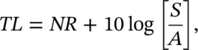
where S is the area of the partition common to both source and receiving rooms and A is the total sound absorption in the receiving room. Note that TL in Eq. (12.78) is known as the sound reduction index (R) in European and ISO standards.
It should be recognized that Eq. (12.72) is approximate only, since it assumes reverberant conditions in both rooms and does not include the direct field in the receiving room. However, in most practical situations Eqs. (12.72) and (12.78) are sufficiently accurate.
EXAMPLE
The sound pressure level on one side of a 3.0 × 4.5 m wall is measured as 90 dB in the 500 Hz octave band. If the transmission loss of the wall is 45 dB in this band and the absorption in the receiving room is 100 sabins (m2), what will the sound pressure level be in the receiving room?
SOLUTION
From Eq. (12.78) we get NR = Lp1 − Lp2 = TL − 10 log (S/A), or
Lp2 = Lp1 − TL + 10 log (S/A) = 90–45 + 10 log (3 × 4.5/100) = 36.3 dB. Note that the absorption in the receiving room has reduced the noise level by 8.7 dB more than what is predicted by simply subtracting the TL value from the sound pressure level in the source room.
b) Standing wave tube method
If a special apparatus is built, it is possible to measure the normal incidence transmission loss of a material sample directly. The apparatus consists of a set of two tubes of equal internal diameter that can be connected to either end of a test sample holder. A schematic drawing of the apparatus is shown in Figure 12.43.
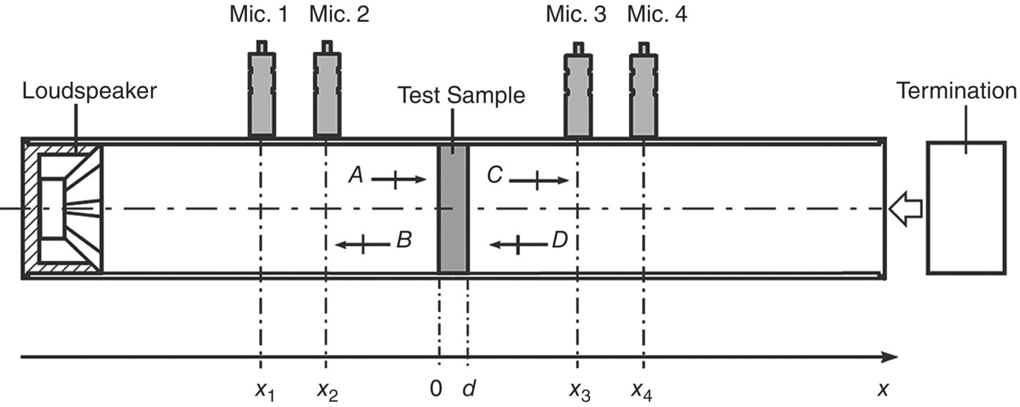
This test method is similar to that used to measure the normal‐incidence sound absorption coefficient, usually called the two‐microphone method [69, 70]. However, for transmission loss, four microphones at two locations on each side of the sample are flush‐mounted in the tube wall. The technique was introduced by Song and Bolton [71] and it has been standardized by ASTM [72]. There is no equivalent ISO standard so far. A loudspeaker is placed at one end of the tube and the other end is closed with a minimally reflecting termination. An anechoic termination should ideally be used.
The loudspeaker is fed with a broadband signal (white noise) and this then radiates plane waves down the tube toward the sample. The resulting standing wave pattern is decomposed into forward‐ and backward‐traveling components by measuring the complex sound pressure simultaneously at the four microphone locations, two on either side of the material sample. Their relative amplitude and phase are determined from the measured transfer function between a reference and the four locations by a multichannel digital signal analyzer. Although a large spacing between the microphones improves the accuracy of the measurements, the microphone spacing must be chosen such that it is less than λ/2. In addition, a careful calibration is required for the measured transfer functions. One of the ways of doing it is the microphone location switching procedure, which prevents the error due to phase mismatch and gain factor between the two sets of measurement channels.
The acoustical transfer matrix is calculated from the acoustic impedance of the traveling waves on either side of the sample. The transmission loss, as well as several other acoustical properties of the material is determined from the transfer matrix. Although this method to determine transmission loss of materials is limited to sound waves normally incident upon the surface of the sample, it provides useful comparison data for small specimens, something that cannot be done in the transmission suite method.
c) Sound intensity probe method
Now that the two‐microphone sound intensity method is so fast and accurate when a digital Fast Fourier Transform analyzer is used, a method was conceived to use this technique to considerable advantage in both laboratory and field measurements of TL. Although the principles of the method were described more than 40 years ago by Crocker et al. [73], the technique was only standardized at the beginning of the twenty‐first century by both ASTM [74] and ISO [75]. The international ISO standard also includes the application of the method for field measurements and laboratory measurements at low frequencies.
The method can be used as an alternative to the transmission suite method for measuring airborne sound insulation of building elements. One important use is when the traditional method fails because of high flanking transmission. The reproducibility of this sound intensity method has been estimated to be equal to or better than that of the transmission suite method. Sound intensity is discussed in more detail in Chapter 8 of this book.
The method can be used in a laboratory setting where the reverberant source room and the specimen mounting conditions satisfy the requirements of the traditional transmission suite method. This method is described in more detail in Chapter 8. The receiving room has no specific acoustical requirements, so in laboratory measurements, only one reverberation room may be used. The acceptability of the receiving room is determined by a set of field indicators that define the quality and accuracy of the sound intensity estimate. Such a procedure reduces the need for two reverberation rooms to one, in sound transmission TL measurements. This can result in a considerable savings, since such facilities are very expensive. Specific details of the method can be found in Chapter 8 and in the following standards [74, 75].
The principle of the method is that the incident sound intensity Ii, is calculated from the diffuse field theory assuming Ii = 〈p2〉/4ρc, where 〈p2〉 is the space average of the room mean square sound pressure. The panel is mounted directly in a hole in one wall of the room, and the transmitted power Wt, from the panel is measured either by traversing a sound intensity probe close to and all over the panel outside of the room (scanning method) or by placing the probe at a set of fixed points to sample the intensity field normal to the panel surface (discrete point method). Then the TL is given directly by TL = 10 log (SIi/Wt), where S is the panel surface area, Wt = SIt and It is the space‐average of the transmitted intensity.
ISO 15186‐2 [76] specifies a sound intensity method for field determination of the sound insulation of walls, floors, doors, windows and small building elements. This method has the advantage that using it, it is possible to determine the energy transmitted directly by the partition and also the energy flanked by walls, floor, and ceiling structures. In addition, the method can be used by transmission suite laboratories, in which the effect of flanking transmission cannot be avoided.
ISO 15186‐3 [77] specifies a method to measure TL at low frequencies, using sound intensity. The method is intended for the frequency range from 50 to 80 Hz. In this method, the sound pressure level of the source room is measured close to the surface of the test specimen. In addition, the surface opposite the test specimen in the receiving room is highly absorbing and converts the room acoustically into a duct with several propagating cross modes above the lowest cut‐on frequency.
Leave a Reply