In order to achieve high TL with a minimum of weight, multiple panels with air spaces between the panels are usually employed. They are used in applications such as aircraft cabin walls and high‐rise buildings where weight savings are important. Higher TL is possible with a multiple‐panel than with a single‐panel partition (of the same mass per unit area), particularly if some absorbing material is introduced into the air spaces and if structural “bridges” between the panels which cause short‐circuiting are minimized.
12.3.1 Sound Transmission Through Infinite Double Panels
The first theories for multiple panels seem to be due to Constable [12] and Kimball [13] in the 1930s. However, a decade later, because of the need to improve the sound insulation of aircraft, Beranek and Work produced one of the most useful and fundamental theories for sound transmission through multiple partitions in 1949 [14]. The theory is restricted to normal incidence sound waves but can, in principle, be simply extended to cover the case of oblique and random‐incidence waves.
The theory rests on the assumption that the particle velocity must be continuous at each boundary as a wave proceeds from left to right. The sound pressure in the air spaces or absorbent layers is given by the solution of the one‐dimensional wave equation:
(12.25)![]()
where A is the wave amplitude, z is the distance from a terminal impedance Zt, b is the propagation constant for the medium, φb = coth−1(Zt/Z0), and Z0 is the characteristic impedance of the medium (i.e. assumed infinite). The impedance
(12.26)![]()
In the air space b = jω/c and Z0 = ρc. In the absorbent layers, b and Z0 will be complex functions of the properties of the material. Beranek and Work then proceeded to determine the impedance seen by a right traveling wave at each interface. From the velocity continuity assumption, the sound pressure ratios across each boundary are deduced to be equal to the relevant impedance ratios.
The theory is found to be very useful and to give reasonable agreement with experiment. Beranek and Work used the flow resistivity (see Section 9.5.3) of various absorbent materials in order to produce “design charts” of panels with various absorbent blankets. The theory does, however, suffer from several shortcomings. First, the theory is only formulated for normal incidence transmission, although it can easily be extended to oblique [15] and random incidence transmission. A more serious shortcoming is the fact that the characteristic impedance is used for the air spaces and absorbent layers and that the “mass law” impedance jωM is used for the impervious panels. It is quite easy to use the infinite panel mechanical impedance (see Section 12.2.1) to allow for stiffness and damping. However, if the panels and air spaces are assumed finite, the analysis becomes complicated, although it can still be formulated in principle.
12.3.2 London’s Theory
London produced two theoretical analyses for the TL of panels. The first, in 1949, was for single panels [16]; the second, in 1950, was for double panels separated by an air space. London’s second theoretical analysis must be acknowledged to be the first for the random incidence of infinite double panels [17]. In both of the analyses, the complete mechanical impedance for the panel (which is assumed to be infinite and very thin) is used (see Section 12.2.1 subsequent to Eq. (12.13)). Unfortunately, however, London included the panel resistance term in an empirical manner and did not relate it to the panel viscous loss factor. It appears that the reason for this (in the case of double panels at least) was that the analysis did not include cavity losses. Thus, London varied his panel resistance term quite arbitrarily with frequency in an attempt to obtain good agreement between theory and experiment. It seems likely that in London’s experiment there was also some cavity absorption, which might explain why London found it necessary to vary the panel resistance in this arbitrary manner.
London’s analysis for a double panel is formulated by considering an incident and reflected wave at the first panel, a standing wave in the air space (represented by the sum of left and right traveling waves), and a transmitted wave. The theoretical model is shown in Figure 12.8. The sound waves in the three regions can be written:

(12.27)![]()

where Pi, Pr, P+, P− and Pt, are the complex amplitudes of the incident, reflected, right traveling, left traveling, and transmitted waves, respectively. These equations may be solved in a similar way to those in Section 12.2.1 by using the two boundary conditions: (i) the normal particle velocity must be continuous at each wall and (ii) the equation of motion at each wall must be satisfied.
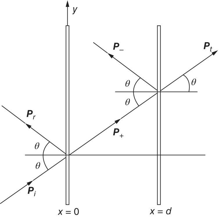
The first boundary condition gives (since for a simple harmonic wave u = (j/ωρ)(∂p/∂x)), at x = 0:
(12.28)![]()
at x = d:
(12.29)![]()
Now the panel velocity must be equal to the particle velocity at each wall; hence,
(12.30)
where vw1 and vw2 are the normal velocities of the two walls. Use of Eqs. (12.27) and (12.30) and the equations of motion for the panel (which are similar to Eqs. (12.5) and (12.7)) enable the two following equations to be written:a
(12.31)![]()
(12.32)![]()
where β = kdcos θ. Using Eqs. (12.28), (12.29), (12.31), and (12.32), the TL may be written:
(12.33)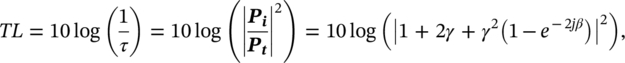
where γ = Zwcos θ /2ρc.
If the wall impedance is assumed to be Zw = jωM, then Eq. (12.33) becomes
(12.34)![]()
where
(12.35)![]()
It is seen from Eq. (12.34) that a wave will be perfectly transmitted if cosβ = a cos θ sinβ, or when
(12.36)![]()
If β is small (d ≪ λ), tanβ ≈ β, and using Eq. (12.35), the lowest frequency for perfect transmission is given approximately by
(12.37)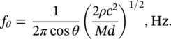
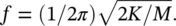
It is quite easy to show that the frequency predicted by Eq. (12.37) is the same resonance frequency (for the case when θ = 0°) which would be predicted for a mass‐spring‐mass system with two masses M coupled together with a cavity spring (stiffness) K of ρc2/d. It is easy to show that the stiffness K of the cavity is ρc2/d, by moving one panel a distance x and computing the change in pressure which results (and thus the stiffness force) when the other panel is kept still. A mass‐spring‐mass system has a resonance frequency
Equation (12.36) will of course, predict higher “resonance” frequencies when there is zero TL (perfect transmission), since there are additional solutions each time β is increased by approximately π (which results from the repeated nature of the tangent curves and the form of Eq. (12.36)). At high frequency, if θ = 0°, then zero TL occurs when β = kd = (2π/λ)d ≈ nπ, where n is an integer. That is equivalent to d ≈ nλ/2 or whenever the panel air gap d is equal to an integer number of half‐wavelengths. Equation (12.34) is plotted in Figure 12.9 for θ = 60° [18]. Note that this plot is given in nondimensionalized form. The frequency f is nondimensionalized in the form f/f0, where f0 is the frequency given by Eq. (12.37) with θ = 0°. The other nondimensional parameter is 2πf0 M/ρc. We see in this figure that θ = 60° and that the fundamental resonance occurs at twice the frequency at which it occurs at normal incidence (θ = 0°). Of more interest, however, is the fact that below the mass‐spring‐mass resonance, the slope of the curves is somewhat less than 6 dB per octave, while above this frequency the slope is much greater (of the order of 12 or 15 dB per octave, or more).
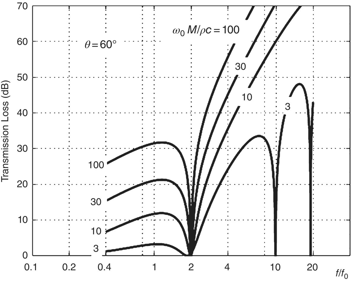
Obviously, as the angle of incidence is increased, so is the first value of f/f0 at which zero TL occurs. For random‐incidence sound, instead of obtaining zero TL at one value of f/f0, we should expect to obtain a “trough” in the TL curve appearing below f0 and continuing into higher frequencies. Unfortunately, Eq. (12.33) cannot be integrated over angle to give a closed‐form solution, as we obtained in the case of a single panel in Eq. (12.21). The transmission coefficient τ in Eq. (12.33) must be averaged over angle θ and integrated numerically. London did this in 1948 by hand before the advent of digital computers, and it was extremely laborious. However, now this integration can be done easily by computer, and London’s theory can be used in designing double partitions. Although useful, London’s theory for double partitions has several limitations. It is assumed that the partitions are infinite in extent and thus it does not take into account partition edge effects. Also, cavity absorption is not taken into account.
EXAMPLE
In a machinery room of a building, there is a noisy 16‐bladed backward‐curved centrifugal fan running at 400 rpm. The neighboring room is used as an administrative office. The partition between the two rooms is composed of a double wall made of two plasterboard (density 692 kg/m3) each having a thickness of 13 mm. The panels are spaced 70 mm apart. Is this a good noise insulation design?
SOLUTION
The mass per unit area of each panel is M = 692 × 13 × 10−3 = 9 kg/m2. The noise from the fan is predominantly at the blade passing frequency (see Chapter 11 of this book), which is calculated as BPF = 16(400)/60 = 107 Hz. The resonance frequency for the double wall is found from Eq. (12.37) for θ = 0°:
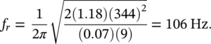
Therefore, it is seen that there is a potential problem since the driving frequency of 107 Hz almost coincides with the resonance frequency of the partition and perfect transmission would be expected. To improve this situation, the resonance frequency must be increased or decreased. A decrease is probably most desirable, and to achieve a sufficient decrease the air gap must be increased to, say, 14 cm and/or the wall mass per unit area increased to 18 kg/m2. A doubling of either d or M theoretically reduces the resonance frequency by a factor of ![]() or 0.707.
or 0.707.
12.3.3 Empirical Approach
In 1978 Sharp [19] presented an empirical approach to estimate the TL of a double partition consisting of two solid panels of different mass per unit area with a cavity between them. The approach gives an approximate way of dealing with the low‐frequency resonances that often limit the sound insulation of lightweight double‐panel walls. Sharp defines three important frequencies: (i) the lowest order acoustic resonance, (ii) the lowest order structural resonance, and (iii) a limiting frequency related to the gap between the panels. The lowest order acoustic resonance is calculated by
(12.38)![]()
where c is the speed of sound in air and L is the longest cavity dimension. The lowest order structural resonance is due to the mass–air–mass resonance; the enclosed air acts as a spring and the panels are the masses. For an air‐filled cavity, this frequency can be approximated by
(12.39)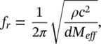
where ρ is the density of air, d is the distance between the inner surfaces, Meff is the effective mass per unit area of the two panels given by Meff = (1/M1 + 1/M2)−1; and M1 , M2 are the masses per unit area of the two layers. Finally, the limiting frequency fl is related to the gap width d between the panels as
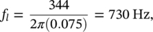
(12.40)![]()
It is common to add sound‐absorbing material to the cavity, which damps cross‐cavity resonances which occur at f1 = c/2d and integer multiples of this frequency. The sound‐absorbing material also lowers the frequency at which the mass–air–mass resonance occurs and leads to higher transmission loss values above fr. As a rough guide, when the wall cavity contains sound‐absorbing material, one can multiply the frequency calculated from Eq. (12.39) by 0.7 to estimate the value of fr [20].
Based on the results presented by Sharp, the following equations can be used to calculate the TL when the two panels in a double‐leaf partition are completely isolated from each other: [4, 6, 10, 20]
(12.41)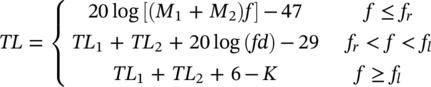
where TL1, TL2 are the transmission losses for each leaf of the double wall measured or calculated separately, and K = 0 if sound‐absorbing material is placed in the air cavity. It is assumed that K = 10log(1 + 2/α) if the cavity is empty, where α is the average sound absorption coefficient of the panel surfaces. Equation (12.41) indicates that, for frequencies between fr and fl, the TL increases by 18 dB for each doubling of frequency (octave), although 15 dB/octave is usually obtained in practice. For frequencies above the limiting frequency fl, the TL of a double wall increases by 12 dB for each doubling of frequency when the cavity is filled with a sound‐absorbing material.
In summary, in a double‐panel wall, high sound insulation can be attained by:
- Selecting a high mass per unit area of the panels.
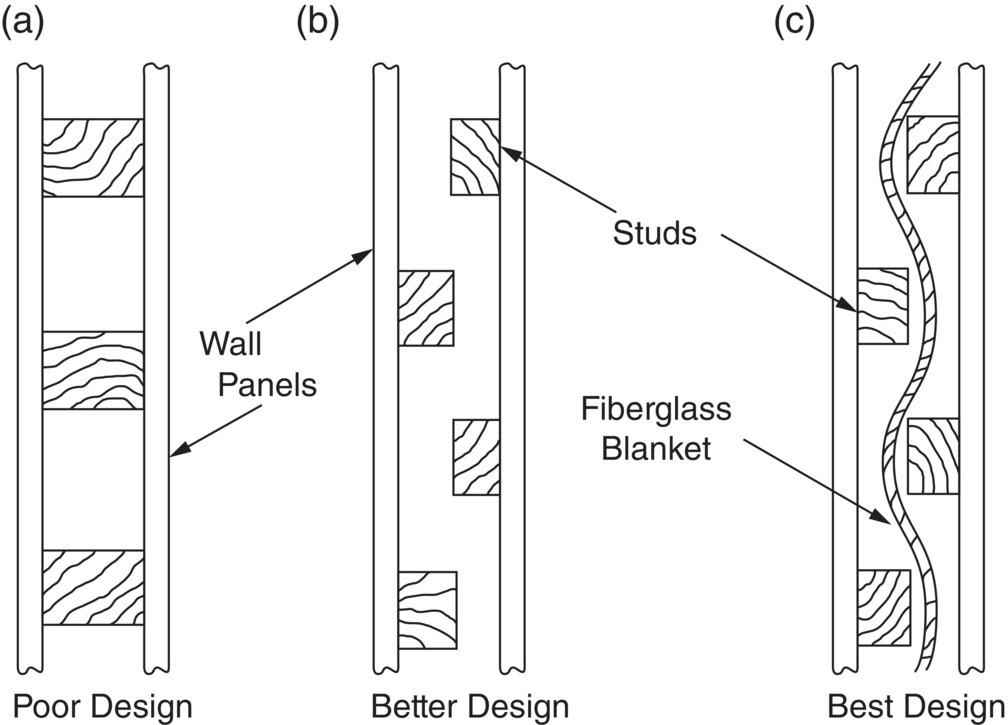
- Avoiding solid connections between the panels: it is found that the use of staggered studs with double panels is particularly effective (see Figure 12.10b). Studs as shown in Figure 12.10a tend to “short‐circuit” the two walls throughout the frequency range and the TL would be lowered by 5–10 dB for such an arrangement.
- Selecting a deep cavity between the panels: the gap width of a double‐panel system affects the TL, particularly at low frequency and the TL may be increased slightly by increasing the gap width.
- Filling the cavity with sound‐absorbing material to ensure a low mass–air–mass resonance frequency: a sound‐absorbing material, such as a fiberglass blanket, placed in the air cavity, as shown in Figure 12.10c, absorbs some of the sound energy in the cavity and raises the TL by 5–10 dB above fr and increases sound transmission class (STC) values about 6–10 dB [20].
- Using different materials having different critical frequencies for each face of the wall, so the coincidence dips are less prominent.
EXAMPLE
Two glass panels (density 2500 kg/m3, cL = 5450 m/s, and η = 0.002), each having a thickness of 6 mm are to be used to reduce the sound transmission through an opening. The panels are spaced 75 mm apart. Assume that the surface sound absorption coefficient for the glass is 0.03 for all frequencies. Obtain the expected TL of the double wall system at the following frequencies: (a) 63 Hz, (b) 500 Hz, (c) 1000 Hz, and (d) 4000 Hz.
SOLUTION
The mass density of each panel is M1 = M2 = 2500 × 0.006 = 15 kg/m2, so Meff = 7.5 kg/m2.
Now, we calculate the mass–air–mass resonance and limiting frequencies for the double wall system, and the critical frequency for each panel as:
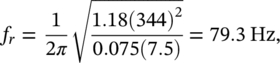
- TL at 63 Hz. Since 63 Hz < fr, TL = 20 log [(15 + 15)63] − 47 = 18.5 dB.
- TL at 500 Hz. Since fr < 500 Hz < fl, the TL for one panel is TL = 20log(15 × 500) − 47 = 30.5 dB. Thus, the TL for the double wall is TL = 30.5 + 30.5 + 20log(500 × 0.075) − 29 = 63.5 dB.
- TL at 1000 Hz. Since 1000 Hz > fl, we obtain

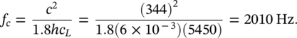
- TL at 4000 Hz. Since 4000 Hz > fl, but 4000 Hz > fc we have to use Eq. (12.24) to determine the TL of each panel as:
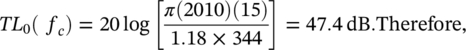
- TL = 47.4 + 10 × log(0.002) +33.22 × log(4000/2010) − 5.7 = 24.6 dB. Now, the TL of the double wall is TL = 24.6 + 24.6 + 6 − 10log[1 + (2/0.03)] = 36.9 dB.
In practice, it is very difficult to construct a double‐panel wall where the two panels are not connected in some way, and the transmission loss predicted by Eq. (12.41) is seldom achieved at high frequencies.
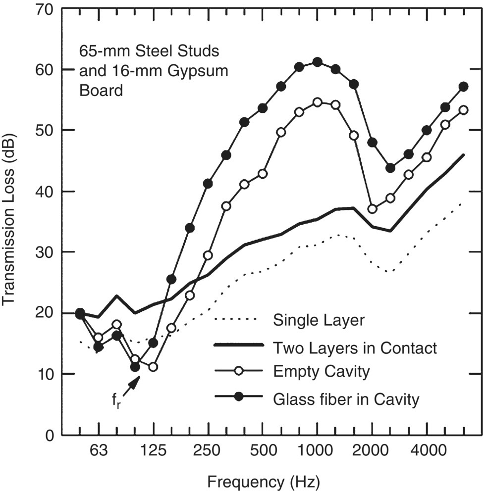
Figure 12.11 shows the transmission loss of 16‐mm gypsum board constructions for four cases: (i) installed as a single sheet, (ii) installed as two panels screwed together as a single leaf, (iii) installed as two panels with a cavity between them, and (iv) installed as two panels with the cavity filled with fiberglass material. We notice that at fr there is a dip in the TL curve that makes the sound insulation less than that for the two sheets in contact, making it even less than that for the single sheet. The TL of the less than double wall becomes equal to that for two panels in contact for frequencies well below fr. Above this resonance frequency, there are very significant improvements in the transmission loss relative to the curve for the two panels in contact.
EXAMPLE 12.7
A double wall without mechanical connections between panels is made of two 16‐mm gypsum boards (density 690 kg/m3, cl = 1850 m/s). The width of the air cavity is 65 mm and it is filled with glass fiber. (a) Determine the TL of this construction at 250 Hz. (b) If the TL of this double wall is greater than 45 dB at 250 Hz, then the partition will fulfill the requirements of sound insulation without increasing the mass per unit area. What is the required gap width d of the double wall?
SOLUTION
- The mass density of each gypsum board is M1 = M2 = 690 × 0.016 = 11 kg/m2, so Meff = 5.5 kg/m2. Now, the relevant frequencies are:
 Now, since fr < 250 Hz < fl, the TL for one panel is TL = 20log(11 × 250) − 47 = 21.8 dB. Thus, the TL for the double wall is TL = 21.8 + 21.8 + 20log(250 × 0.065) − 29 = 38.8 dB
 - We may use the second of Eq. (12.41) to solve the problem but we must check that 250 Hz is between the new fr and fl. Thus, TL = 21.8 + 21.8 + 20log(250 × d) − 29 = 45 dB. Solving for d, we obtain that d = (1/250)1030.4/20 ≈ 0.13 m. Using this gap width, we obtain that fr = 70 Hz and fl = 421 Hz, so fr < 250 Hz < fl. Therefore, a gap width of 13 cm will fulfill the insulation requirements.
Leave a Reply