Valve‐Induced Noise
Control valves are used in industrial plants to control the rate of fluid flow by creating a pressure drop across the valve. The flow is first accelerated by this process and then the kinetic energy is converted into thermal energy or heat through turbulence and/or shock waves. In the process a small fraction of the energy is converted into acoustical energy and thus noise. The aerodynamic noise generated by control valves, regulators, and orifices is a major noise source in piping systems. In some cases, exterior noise levels as high as 130 dB can be produced. In addition, in liquid flow systems, hydrodynamic noise (which is mostly due to cavitation) is of some importance. However, in most industrial situations, with high‐speed gas flows, the aerodynamic noise is dominant [85]. The main noise‐generating mechanisms include turbulent mixing, turbulence interaction with boundaries, cavitation in liquids, shock waves, interaction of turbulence with shocks, cavity resonances, flow separation, vortex shedding, “whistling,” and resonant mechanical vibration of valve components [86, 87]. Figure 11.24 presents a simplified view of a control valve and some of the noise sources [87]. See Ref. [88] for an extensive discussion on this subject. Comprehensive reviews of control valve noise have also been given by Reethof [86, 87]. Seebold has reviewed control valve noise sources and approaches for noise control [89].
![Schematic representation of control valve noise generation and propagation [87].](https://learning.oreilly.com/api/v2/epubs/urn:orm:book:9781118496428/files/images/c11f024.gif)
The major noise‐generating processes can be divided into two regimes: subsonic, consisting mostly of turbulence–boundary interaction noise, and supersonic, consisting mainly of broadband shock noise. Although the flow is confined by the piping, the turbulent mixing noise is similar to the noise of a free jet and is essentially quadrupole in nature [90, 91]. The shocks are caused by abruptly expanded flow after the valve, when it is operating above the critical pressure ratio. The shock noise has two main parts: screech and broadband noise. The screech is discrete in nature and is caused by a feedback mechanism and is not often encountered with valves and regulators. The broadband shock noise is common, however, and has been shown to be mostly independent of flow velocity and to be a function of the pressure ratio across the valve.
Valve noise prediction is quite complex and computational tools are often the only way to compute the noise radiated. However, although not as accurate as a computerized method some simplified noise prediction graphical techniques are available. Figure 11.25 shows a graphical technique from The International Society of Measurement and Control (ISA). Use of the method is described by Baumann and Abom [88] as: First, find the P1/P2 ratio, that is, the absolute inlet pressure divided by the absolute outlet pressure. Next read up to the given valve size and obtain the corresponding “basic sound pressure level” A from the scale on the left. The next step is to correct for the actual inlet pressure. This is given by B = 12log(P1/667) where the pressure is in kilopascals. Finally, add C, a correction for the pipe wall if it is other than Schedule 40. Here C = +1.4 for Schedule 20, 0 for Schedule 40, −3.5 for Schedule 80, and −7 for Schedule 160. The total A-weighted sound pressure level now is the sum of A + B + C. Subtract another 3 dB in case of steam. The following example shows how to use this method [88].
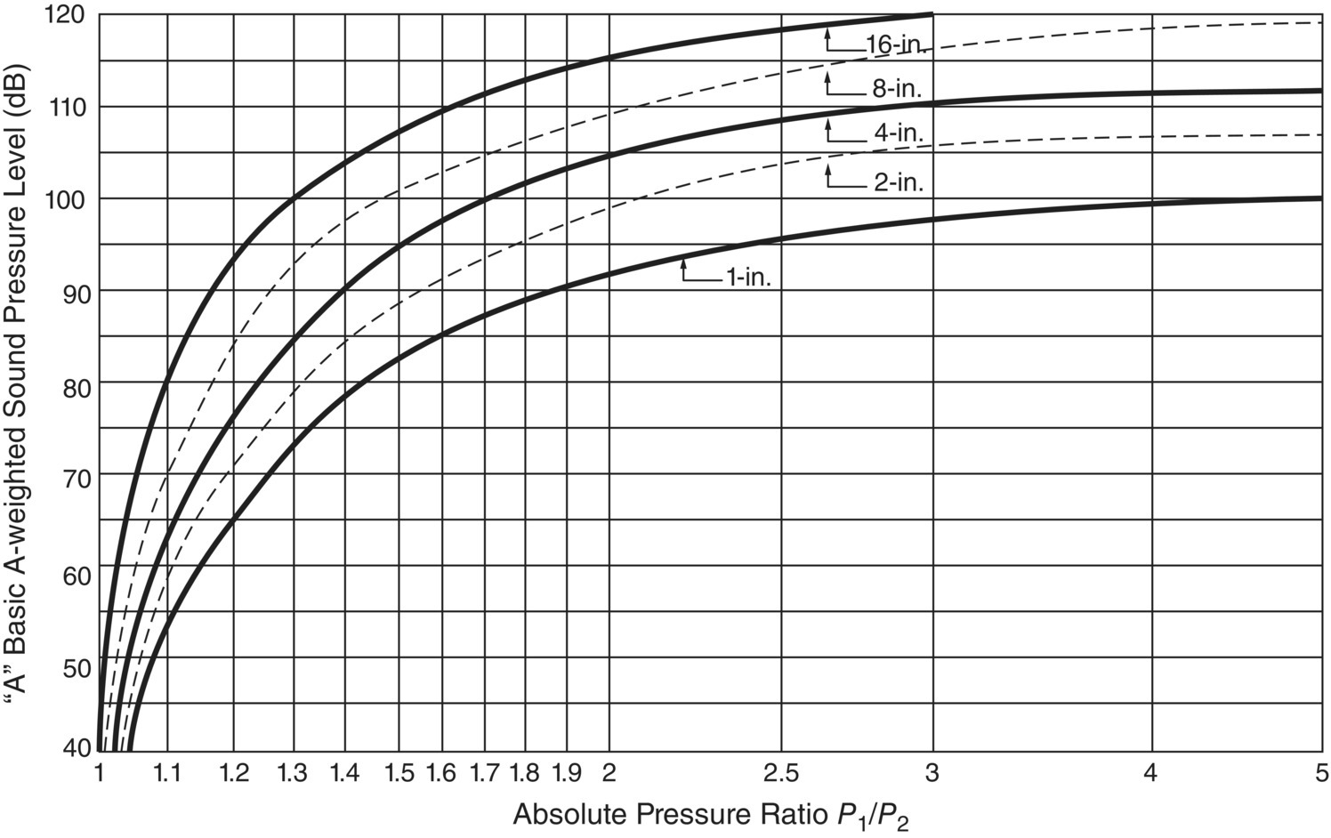
EXAMPLE 11.11
An 80‐mm (3‐in.) globe valve with a parabolic plug is reducing steam pressure from 3600 to 2118 kPa. Considering that the pipe Schedule is 80, determine the total A‐weighted sound pressure level at 1 m from the pipe.
SOLUTION
The pressure ratio is 3600/2118 = 1.7. Going to Figure 11.25, we do not find a 3‐in. valve. However, we can extrapolate between the lines and find the A factor to be 98 dB for the pressure ratio of 1.7. Factor B is calculated to be 12log(3600/667) = 8.8 dB. Finally, we add −3.5 dB for Schedule 80 and we subtract 3 dB for steam. This results in a total A‐weighted sound pressure level of 100.3 dB at 1 m from the pipe wall.
EXAMPLE 11.12
Using a computational method, the A‐weighted sound pressure level produced by a valve at 1 m from pipe wall is estimated to be 105 dB. What would the sound pressure level be for a worker 30 m away from the downstream pipe (centerline)?
SOLUTION
Noise produced by valves radiates to the environment largely through the pipe for great distances downstream of a valve. Therefore, this type of noise source is usually treated as a line source (see Section 3.10 of this book). Line sources radiate noise in a cylindrical pattern and the sound pressure is reduced by 3 dB per doubling of the distance. Then, the reduced A‐weighted sound pressure level at 30 m from the line source is Lp(30 m) = Lp(1 m) − 10 × log(30 m/1 m) = 105 − 15 = 90 dB.
Valve noise can be reduced by several approaches including design of valves with multiple streams, arranging for the pressure drop to occur through several stages, and using absorptive silencers, thicker pipe walls, and pipe lagging. Multiple stream valve designs and absorptive silencers are effective at reducing noise. Absorptive silencers can produce noise reductions of as much as 15–30 dB. However, such silencers can become plugged by solid particles and moisture can be a problem in the silencer material so that effectiveness is lost. Reference [88] deals in detail with noise‐generating mechanisms and the prediction and control of control valve noise. Several other authors have also given helpful reviews of valve and piping system noise, and the reader is referred to these as well for more detailed discussions [15, 85–87, 89].
11.4.2 Hydraulic System Noise
Noise in a hydraulic circuit is usually produced by the pumps and motors, although valves are also important noise sources. Many high‐pressure hydraulic fluid power systems use positive‐displacement pumps. The diameter of pipes used in such systems is usually quite small (of the order of 10–50 mm). The flow is normally single phase with negligible gas bubble and solid particle content. The usual operating pressures are of the order of 100–300 bars. There are systems, however, which operate at pressures of up to 500 or even 650 bars. Hydraulic systems often produce very high noise levels that can limit the range of applications of fluid power systems. Potential high‐level noise problems can result in the selection of an alternative means of power transmission in cases where low‐noise systems are required.
Hydraulic system noise sources may be categorized as follows: (i) Airborne noise originates from the vibration of components, piping, and housings, and is transmitted directly through the air. (ii) Structure‐borne noise is caused by the mechanical operation of pumps and motors and is transmitted from pumps directly through mounts, drive shafts, and pipes. Structure‐borne noise can also arise from the pressure “ripple” in the hydraulic system. (iii) Fluid‐borne noise is caused primarily by unsteady flow from the pumps and motors but can also be caused by valve instability, cavitation, and/or turbulence.
Fluid‐borne noise can be transmitted over considerable distances through pipework with little attenuation. Figure 11.26 gives an illustration of (a) structure‐borne noise and (b) fluid‐borne noise (commonly called ripples) created by a multipiston axial‐flow pump [92].
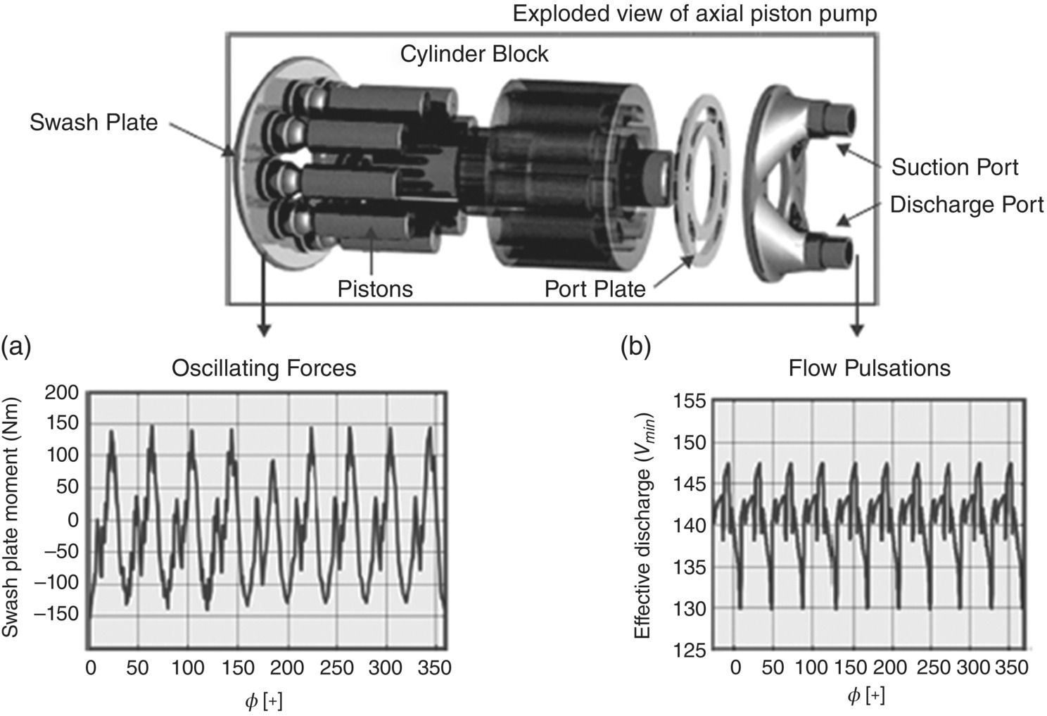
The main sources of noise in a hydraulic system are usually the pumps and motors. Valves are also important noise generators. See Ref. [88] for further discussion on valve noise. Positive‐displacement pumps are mainly used in fluid power applications. The most common types are piston pumps, gear pumps, and vane pumps. See Ref. [76] for more detailed discussion on pump noise. Positive‐displacement pumps produce a steady fluid flow rate on which is superimposed a flow fluctuation or ripple, which is caused by the cyclic nature of the pump operation. The flow ripple is also manifested as a pressure fluctuation or ripple. The magnitude of the flow ripple depends on the pump type and its operating conditions [92, 93]. Flow ripple normally occurs in both the suction and the discharge lines. Usually the discharge flow ripple is the most important noise source. Fluid‐borne noise in the suction line may cause noise problems especially when it causes vibration and noise radiation from a large‐surface reservoir.
There are several ways of reducing the noise of hydraulic systems [90, 92] These include (i) reduction of the pump or motor flow ripples [75] (personal communication with Cesare Angeloni, 9 February 2006), (ii) tuning of the circuit in order to avoid resonant conditions, (iii) use of silencers or pulsation dampers, (iv) use of flexible hoses [74], (v) vibration isolation [74], and (vi) use of enclosures or pipe cladding.
11.4.3 Furnace and Burner Noise
The phenomenon of thermoacoustically‐induced oscillations and combustion noise, or “roar,” in combustion systems is complicated and usually only qualitative explanations can be given [94]. Various empirical methods have been developed to predict combustion noise. In practice, engineering solutions are mainly used to control combustion oscillations and noise.
Combustion systems consist of two main fuel and air delivery system components: (i) burner and (ii) combustor. The fuel injection component is usually called the burner. The element within which the heat release takes place is normally referred to as the combustor or furnace. The purpose of combustion systems is to add heat to an airstream. The main mechanisms that produce combustion noise are common to all combustion systems. The purpose of the fuel burner is to mix and direct the flow of fuel and air to ensure rapid ignition and complete combustion within the furnace or combustor [94]. The combustion of gaseous fuels takes place mainly in two ways: (i) when the gas and air are mixed before ignition, known as premix flames, and (ii) when the gas and air are mixed after the fuel has been heated, known as diffusion flames.
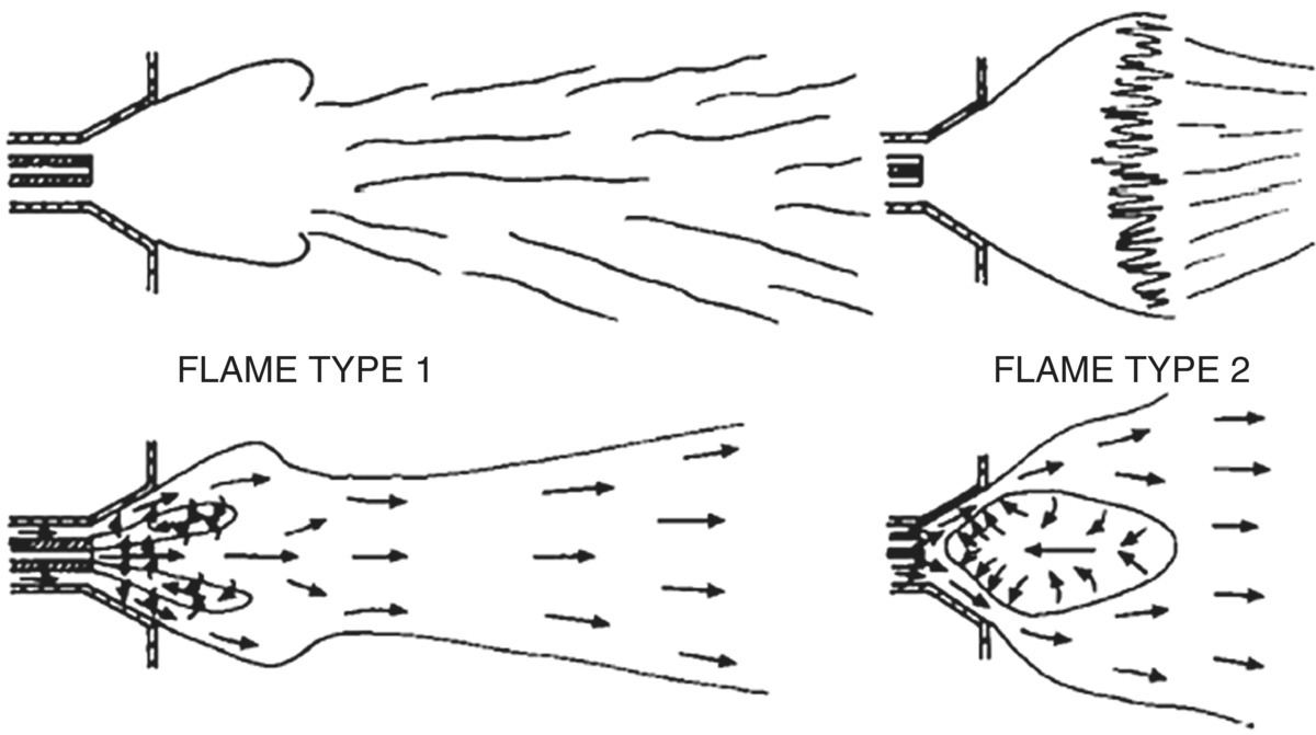
The noise generated by the combustion can be considered to be either (i) combustion roar or (ii) combustion‐driven oscillations or thermoacoustic instabilities. The latter type of noise is observed when pressure oscillations are induced by heat release oscillations. Although thermoacoustic instabilities are closely related to flame instabilities, their instability criteria are different. The main focus of Ref. [94] is on thermoacoustic instabilities since they can produce higher sound pressure levels than combustion roar and since they also have a greater potential for structural damage. It should be noted that some researchers further subdivide combustion noise into four categories [95, 96]. Figure 11.27 shows two types of flame. Type 1 flames tend to be relatively quiet and type 2 flames tend to be relatively noisy. It has been found by several researchers that if sufficient swirl is introduced into the flow, flames change from type 1 to type 2 [95–98].
There are two main passive noise control measures available: (i) reducing the combustion‐induced sources and (ii) use of traditional noise control approaches including use of absorptive mufflers, acoustical resonators, enclosures for the burner, furnace, or boiler or other units to which they are attached. Active approaches to control thermoacoustic oscillations have also been attempted
Leave a Reply