Fans and blowers are used in appliances, in buildings, in air distribution systems for heating and cooling, and in industry for a variety of purposes. Fan noise, its generation, and control are discussed in detail in Ref. [31] and Chapter 13 in the present book. There are two main types of fan designs: axial and centrifugal (see Figure 11.7). The first three centrifugal fan types – airfoil, backward‐curved, and radial – are mostly used in industrial applications. The airfoil fan is the most efficient but it is only suitable for clean‐air industrial applications because dust and other particles can adhere to the fan blades and cause malfunctioning.
The forward‐curved fan is usually made of lightweight low‐cost materials and is generally the least efficient. The radial fan is the noisiest and least efficient but is useful for dirty or corrosive gas flows. Axial fans have the disadvantage that the discharged air rotates, unless downstream or upstream guide vanes (stators) are installed; these fans are mainly used in low‐ or medium‐pressure air‐conditioning systems. The vane‐axial fan is the most efficient axial type and can generate high pressures. The propeller type is the least expensive of the axial type. It has the lowest efficiency and is normally limited to low‐pressure, high‐volumetric flow applications. The primary purpose of a fan is to move a required volumetric flow rate of air against a given back pressure with maximum efficiency and low cost and noise. There may be additional requirements such as high resistance to abrasion, ability to transport dusty air, ease of manufacture, maintenance and repair, and noise restrictions.
Fan noise has pure‐tone and broadband frequency components. Although the mathematical theory of fan noise is well developed, it is beyond the scope of this chapter, and physical explanations are presented instead. Noise from fans is caused by several mechanisms that have been summarized by Lauchle in Figure 11.8 [31].
Each time a blade passes a point in space or a solid‐body obstruction, an impulsive force fluctuation is experienced by the fluid or solid body at the point. If a fan has n equally‐spaced blades and the rotational speed is N rpm, then the number of impulses experienced per second fB is
(11.7)![]()
The frequency fB is known as the blade passing frequency ( BPF ) or often the blade frequency for short. Since the time history of the impulsive force on the fluid or solid‐body obstruction will not be completely sinusoidal, harmonics will appear. The strength of the harmonics is affected by upstream or downstream solid‐body flow obstructions.
The noise generated by a fan depends primarily on its design features, geometrical dimensions, and operating speed and load. Both broadband and pure‐tone fan noise normally increase with increasing fan speed N. The frequency of the pure‐tone noise generated by a fan increases with fan speed N as shown by Eq. (11.7).
The overall sound power in watts of a fan of rotor diameter D can be approximately predicted by [31]
(11.8)![]()
Equation (11.8) indicates that the overall sound power at a constant point of operation is proportional to D7 and increases as the fifth power of the fan speed. Other important dimensionless parameters in fan design are the flow coefficient ϕ and the static pressure coefficient ψ, given by
(11.9)![]()
and
(11.10)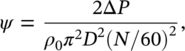
where Q is the volumetric flow rate (m3/s), ΔP is the static pressure rise (Pa), and ρ0 is the air density (kg/m3).
EXAMPLE 11.4
Consider a fan of diameter 0.4 m operating at 3000 rpm. Find either a new diameter or new operating speed to achieve a 10‐dB noise reduction.
SOLUTION
The noise reduction is ΔLw = 10 log (W1/W) = −10 dB, where W1 is the overall sound power of the modified fan (see Eq. (11.8)).
- At constant operating speed, we have:
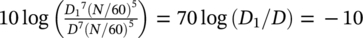 . Therefore, D1 = D × 10−1/7 = 0.72 × D = 0.72 × 0.4 = 0.29 m.
 - At constant diameter:
 , so N1 = N × 10−1/5 = 0.63 × N = 0.63 × 3000 = 1893 rpm.
Thus, we can change the diameter to 29 cm or change the fan speed to 1893 rpm to obtain a 10‐dB overall noise reduction while maintaining the same value of ϕ and ψ. However, the performance of the fan will suffer because of the noise reduction enforced. Thus, one needs to decide from the application whether these decreases in performance are justified. Equations (11.9) and (11.10) show that at constant speed, the flow rate is proportional to D3 and the pressure rise to D2. The new flow rate would be Q1 = (0.72)3 Q = 0.37Q and the new static pressure rise would be ΔP1 = (0.72)2ΔP = 0.52ΔP. On the other hand, at constant diameter, these new values are Q1 = (0.63)3 Q = 0.25Q and ΔP1 = (0.63)2ΔP = 0.40ΔP. Therefore, if flow rate is more important than static pressure rise, one might choose to lower the fan speed to obtain the required noise reduction [31].
Structural resonances can also be excited in a fan. These resonance frequencies are largely independent of fan speed. If the fan is operated at off‐design conditions, its noise can also be higher than normal. If the fan is operated at reduced volumetric flow rates, the A‐weighted sound pressure level can be as much as 15 dB higher than normal because of fan surge and rotating fan stall.
Fan sound power level data are normally provided by manufacturers. Table 11.2 gives specific sound power levels (ref: 10−12 watts) in eight octave bands from 63 to 8000 Hz for different types of fans and blowers [31]. This table, based on the research of Graham and Hoover [32] and others, provides an empirical method for predicting the noise of axial and centrifugal fans. In order to account for flow rate and static pressure rise, simply add 10log Q + 20 log ΔP (with Q in m3/s and ΔP in kPa) to the tabulated values. The last column in Table 11.2 gives the value to be added to the level of the particular octave band in which the BPF falls.
Table 11.2 Specific sound power levels, dB, in eight lowest one‐octave bands for a variety of axial and centrifugal fans [31].
| Fan type | Rotor diameter (m) | One‐octave band center frequency (Hz) | ||||||||
|---|---|---|---|---|---|---|---|---|---|---|
| 63 | 125 | 250 | 500 | 1000 | 2000 | 4000 | 8000 | Add for BPF | ||
| Backward‐curved | >0.75 | 85 | 85 | 84 | 79 | 75 | 68 | 64 | 62 | 3 |
| centrifugal | <0.75 | 90 | 90 | 88 | 84 | 79 | 73 | 69 | 64 | 3 |
| Forward‐curved | All | 98 | 98 | 88 | 81 | 81 | 76 | 71 | 66 | 2 |
| centrifugal | ||||||||||
| Low‐pressure radial | >1.0 | 101 | 92 | 88 | 84 | 82 | 77 | 74 | 71 | 7 |
| 996 ≤ ΔP ≤ 2490 | <1.0 | 112 | 104 | 98 | 88 | 87 | 84 | 79 | 76 | 7 |
| Midpressure radial | >1.0 | 103 | 99 | 90 | 87 | 83 | 78 | 74 | 71 | 8 |
| 2490 ≤ ΔP ≤ 4982 | <1.0 | 113 | 108 | 96 | 93 | 91 | 86 | 82 | 79 | 8 |
| High‐pressure radial | >1.0 | 106 | 103 | 98 | 93 | 91 | 89 | 86 | 83 | 8 |
| 4982 ≤ ΔP ≤ 14 945 | <1.0 | 116 | 112 | 104 | 99 | 99 | 97 | 94 | 91 | 8 |
| Vane‐axial | ||||||||||
| 0.3 ≤ Dh /D ≤ 0.4 | All | 94 | 88 | 88 | 93 | 92 | 90 | 83 | 79 | 6 |
| 0.4 ≤ Dh /D ≤ 0.6 | All | 94 | 88 | 91 | 88 | 86 | 81 | 75 | 73 | 6 |
| 0.6 ≤ Dh /D ≤ 0.8 | All | 98 | 97 | 96 | 96 | 94 | 92 | 88 | 85 | 6 |
| Tube‐axial | >1.0 | 96 | 91 | 92 | 94 | 92 | 91 | 84 | 82 | 7 |
| <1.0 | 93 | 92 | 94 | 98 | 97 | 96 | 88 | 85 | 7 | |
| Propeller | All | 93 | 96 | 103 | 101 | 100 | 97 | 91 | 87 | 5 |
EXAMPLE 11.5
Estimate the total sound power level of a 24‐bladed forward‐curved centrifugal fan running at 2400 rpm. The fan delivers a volume flow rate Q = 20 m3/s against a static pressure of 5 kPa.
SOLUTION
We must calculate the BPF using Eq. (11.7), BPF = 24 × 2400/60 = 960 Hz. Now, we calculate 10 log Q + 20 log ΔP = 10 log (20) + 20 log (5) = 13 + 14 = 27 dB.
Thus, referring to the third row of Table 11.2 we must add 27 dB to the values of sound power levels for all one‐octave bands, and we must also add 2 dB at the 1000 Hz one‐octave band where the BPF falls. Therefore, the sound power levels in eight one‐octave bands from 63 to 8000 Hz are: 125, 125, 115, 108, 110 (108 + 2), 103, 98, and 93 dB, respectively. The overall sound power level is obtained by logarithmically adding the previous one‐octave band levels. Then,

As discussed in Example 11.4 it is difficult to reduce fan noise by changing fan design parameters since such changes may adversely affect fan performance as well. Most fan noise reduction is achieved by proper use of well‐known passive control methods. If noise is of major concern and the fan has been properly installed, it will probably be necessary to install intake and discharge sound attenuators (with flexible vibration breaks at attachment points to duct systems, if present). It is also possible to provide further noise attenuation by the use of ducting, elbows, and plenum chambers lined with sound‐absorbing material. Care must be taken that significant noise is not generated in this ductwork. Chapter 13 in the present book and Ref. [33] describe the prediction and control of the noise and vibration in ducted heating, ventilation, and air‐conditioning systems, and Ref. [34] discusses the aerodynamic sound generated in low‐speed flow ducts.
Use of tuned resonators such as cavities for controlling tones is another passive noise control technique. For axial fans, the cavity can be integrated into the hub. In centrifugal fans a cavity can be installed in the cutoff region. The cavity must have rigid walls and designed to be a one‐quarter wavelength long at the BPF. The application of this method to a 44‐blade centrifugal blower is shown in Figure 11.9.
Considerable efforts continue to be made to reduce fan noise since fans are used in most computers, electric motors, household appliances, vehicles, trucks, and many other items of machinery. Numerous studies have been conducted on the noise control of fans [30, 35–49]. Both passive [30, 35–43] and active [44–48] noise control methods continue to be studied. Experimental and theoretical studies have been made to aid in machinery noise reduction and noise predictions. Sound quality studies have also been conducted on the acceptability of fan noise
Leave a Reply