Sound‐absorbing materials have been found to be very useful in the control of noise. They are used in a variety of locations: close to sources of noise (e.g. close to sources in electric motors), in various paths, (e.g. above barriers in buildings or inside machine enclosures), and sometimes close to a receiver (e.g. inside earmuffs). When a machine is operated inside a building, the machine operator usually receives most sound through a direct path, while people situated at greater distances receive sound mostly through reflections (see Figure 9.11).
The relative contributions of the sound reaching people at a distance through direct and reflected paths are determined by how well the sound is reflected and absorbed by the walls in the building.
9.5.1 Sound Absorption Coefficient
When sound waves strike a boundary separating two media, some of the incident energy is reflected from the surface and the remaining energy is transmitted into the second medium. Some of this energy is eventually converted by various processes into heat energy and is said to have been absorbed by that medium. The fraction of the incident energy absorbed is termed the absorption coefficient α(f), which is a function of frequency and already defined in Chapter 3 as
(9.7)![]()
The absorption coefficient theoretically ranges from zero to unity. In practice, values of α > 1.0 are sometimes measured. This anomaly is due to the measurement procedures adopted to measure large scale building materials. One sabin is defined as the sound absorption of one square metre of a perfectly absorbing surface, such as an open window. The sound absorption of a wall or some other surface is the area of the surface, in square metres, multiplied by the absorption coefficient.
9.5.2 Noise Reduction Coefficient
Another parameter, which is often used to assess the performance of an acoustical absorber, is the single number known as the noise reduction coefficient (NRC). The NRC of a sound‐absorbing material is given by the average of the measured absorption coefficients for the 250‐, 500‐, 1000‐, and 2000‐Hz one‐octave bands rounded off to the nearest multiple of 0.05. This NRC value is often useful in the determination of the applicability of a material to a particular situation. However, where low or very high frequencies are involved, it is usually better to consider sound absorption coefficients instead of NRC data.
EXAMPLE 9.4
If α250 = 0.25, α500 = 0.45, α1000 = 0.65, and α2000 = 0.81, what is the NRC?
SOLUTION

A wide range of sound‐absorbing materials exist that provide absorption properties dependent upon frequency, composition, thickness, surface finish, and method of mounting. They can be divided into several major classifications. Materials that have a high value of α are usually porous and fibrous. Fibrous materials include those made from natural or artificial fibers including glass fibers. Porous materials made from open‐celled polyurethane are also widely used.
9.5.3 Absorption by Porous Fibrous Materials
Porous materials are characterized by the fact that the nature of their surfaces is such that sound energy is able to enter the materials by a multitude of small holes or openings. They consist of a series of tunnel‐like pores and openings formed by interstices in the material fibers or by foamed products. (Usually, within limitations, the more open and connecting these passages are, the larger are the values of the sound‐absorbing efficiency of the material.) If, on the other hand, the pores and penetrations are small and not joined together, then the material becomes substantially less efficient as a sound absorber. Included in this broad category of porous absorbers are fibrous blankets, hair felt, wood‐wool, ceramics, foams, acoustical plaster, a variety of spray‐on products, and certain types of acoustical tiles [59].
When a porous material is exposed to incident sound waves, the air molecules at the surface of the material and within the pores of the material are forced to vibrate and in the process lose energy. This is caused by the conversion of sound energy into heat due to thermal and viscous losses of air molecules at the walls of the interior pores and tunnels in the sound‐absorbing material. At low frequencies these changes are isothermal, while at high frequencies they are adiabatic. In fibrous materials, much of the energy can also be absorbed by scattering from the fibers and by the vibration caused in the individual fibers. The fibers of the material rub together under the influence of the sound waves and lose energy due to work done by the frictional forces. Figure 9.12 shows the two main mechanisms by which the sound is absorbed in materials. For this reason, high values of absorption coefficient in excess of 0.95 can be observed. Depending upon how α is determined experimentally, values in excess of unity can also be measured [60]. The values of α observed are usually strongly dependent upon (i) frequency, (ii) thickness, and (iii) method of measurement. These should always be considered in the choice of a particular material.
Figure 9.13 shows typical sound absorption characteristics for a blanket‐type fibrous porous material placed against a hard wall, and with a 10‐cm airspace between the material and the wall. In both cases the absorption properties are substantially better at high frequencies than low. When the same material is backed by an airspace, the low‐frequency absorption is improved without significantly changing the high‐frequency characteristics. Hanging drapes and curtains a few centimeters away from walls and windows can improve their sound absorption properties, particularly at low frequencies. Figure 9.14 shows the effect of increasing the thickness of sound‐absorbing materials mounted on solid backings. Increased low‐frequency absorption is also observed for increased material thickness.
An additional effect to consider is that of surface treatment, since most materials will become discolored or dirty after prolonged exposure for several years and may require cleaning or refinishing. Because the surface pores must be open to incident sound for the porous material to function, it is essential that they should not be blocked with paint or any other surface‐coating treatment. The effects of brush painting porous materials are usually more severe than spray painting; however, the usual effect is to lower the absorption coefficient to about 50% of its unpainted value particularly at high frequencies. In addition, the absorption peak is shifted downward in frequency. As more coats of paint are applied, the paint membrane becomes denser and more pores are sealed, the result of which is to shift the absorption peak even lower in frequency and magnitude.
It is useful now to describe briefly the physical parameters used to account for the sound‐absorbing and attenuating properties of porous materials. These include flow resistivity, porosity, volume coefficients of elasticity of both air and the skeleton, structural form factor (tortuosity), and specific acoustic impedance. These will each be described separately.
a) Flow Resistivity R
This accounts for the resistance offered to airflow through the medium. It is defined in the meter–kilogram–second (mks) system as
(9.8)![]()
where R is the flow resistivity (mks rayls/m), Δp is the differential sound pressure created across a sample of thickness t, measured in the direction of airflow (N/m2), U is the mean steady flow velocity (m/s), and t is the thickness of the porous material sample (m). Typical values for porous fibrous materials vary from 4 × 10³ to 4 × 10⁴ mks rayls/m for a density range of 16 kg/m3–160 kg/m3. Generally speaking, if the flow resistivity R becomes very large, then most of the incident sound falling on the material will be reflected; while if R is too small, then the material will offer only very slight viscous losses to sound passing through it, and so it will provide only little sound absorption or attenuation. Although the absorption is proportional to thickness, it is generally found that for a given flow resistivity value R, the optimum thickness of material is approximately given by t = 100/ ![]() .
.
b) Porosity ε
The porosity of a porous material is defined as the ratio of the void space within the material to its total displacement volume as
(9.9)![]()
where Va is the volume of air in the void space in the sample and Vm is the total volume of the sample. It has to be noticed that the void space is only that accessible to sound waves. For a material composed of solid fibers the porosity can be estimated from
(9.10)![]()
where Ms is the total mass of sample (kg), Vs is the total volume of sample (m3), and ρF is the density of fibers (kg/m3). Typical values of porosity for acceptable acoustical materials are greater than 0.85.
c) Volume Coefficient of Elasticity of Air K
The bulk modulus of air is derived from
(9.11)![]()
where Δp is the change in pressure required to alter the volume V by an increment ΔV (N/m2), ΔV is the incremental change in volume (m3), and K is the volume coefficient of elasticity for air (N/m2).
d) Volume Coefficient of Elasticity of the Skeleton Q
This is defined in a similar way to the bulk modulus. It is derived from the change in thickness of a sample sandwiched between two plates as the force applied on them is increased, that is,
(9.12)![]()
where δF is the incremental force applied to the sample (N), δt is the incremental change in thickness of the sample (m), t is the original thickness (m), Q is the volume coefficient of elasticity of the skeleton (N/m2), and S is the sample area (m2).
e) Structural Form Factor k s
It is found that in addition to the flow resistance, the composition of the inner structure of the pores also affects the acoustical behavior of porous materials. This is because the orientation of the pores relative to the incident sound field has an effect on the sound propagation. This has been dealt with by Zwikker and Kosten [61] and treated as an effective increase in the density of the air in the void space of the material. Beranek [62] reports that flexible blankets have structure factors between 1.0 and 1.2, while rigid tiles have values between 1.0 and 3.0. He also shows that, for homogeneous materials made of fibers with interconnecting pores, the relationship between the porosity ε and structure factor ks is ks ≈ 5.5–4.5ε. In the technical literature it is possible to find the self‐explanatory term tortuosity used instead of structural form factor. For most fibrous materials the structural form factor is approximately unity.
f) Specific Acoustic Impedance z0
This is defined as the ratio of the sound pressure p to particle velocity u at the surface of the material, for a sample of infinite depth, when plane sound waves strike the surface at normal incidence. This is a complex quantity and it is defined mathematically as
(9.13)![]()
where z0 is the normal specific acoustic impedance, ρc is the characteristic impedance of air (415 mks rayls), and j = ![]() ; rn and xn are the specific acoustic resistance and specific acoustic reactance, respectively.
; rn and xn are the specific acoustic resistance and specific acoustic reactance, respectively.
It is useful to briefly examine some of the interesting relationships that exist between the specific impedance and the absorption coefficient α under certain circumstances. For example, if a porous material is composed so that rn ≫ 1 and rn ≫ xn, the absorption coefficient αθ for a sound wave striking a surface at angle θ to the normal is given by
(9.14)
Furthermore, for a diffuse sound field, the random incidence absorption coefficient α is given by [14]
(9.15)
If rn > 100 (materials with small absorption coefficients), this equation can be substantially simplified to α = 8/rn.
The use of the complex acoustic impedance, rather than absorption coefficient, allows for a much more rigorous treatment of low‐frequency reverberation time analysis for rooms. Although often considerably more complex than the classical theory, this approach does predict more accurate values of reverberation times in rooms containing uneven distribution of absorption material, even if either pair of opposite walls are highly absorbing or if opposite walls are composed of one very soft and one very hard wall [14]. Beranek shows [62, 63] that the specific acoustic impedance of a rigid tile can be written in terms of the previously defined fundamental parameters as
(9.16)
where ρ is the density of air (kg/m3) and ω is the angular frequency (rad/s). It can therefore be seen from Eqs. (9.13), (9.15), and (9.16) that the absorption coefficient is proportional to the porosity and flow resistance of the material (provided rn > 100 and rn ≫ xn), and is inversely proportional to the density and structure factor. For soft blankets, the expressions for the acoustic impedance become very much more complex and the reader is directed to Refs. [61–63] for a much more complete analysis.
The basic theory used to model the sound propagation within porous absorbents assumes that the absorber frame is rigid and the waves only propagate in the air pores. This is the typical case when the porous absorber is attached to a wall or resting on a floor that constrains the motion of the absorber frame. Neglecting the effect of the structural form factor, it can be shown that plane waves in such a material are only possible if the wavenumber is given by [64]
(9.17)
where k is the free‐field wavenumber in air (m−1) and ρ is the density of air (kg/m3). In addition, the wave impedance of plane waves is
(9.18)![]()
In another method of analysis, a fibrous medium is considered to be composed of an array of parallel elastic fibers in which a scattering of incident sound waves takes place resulting in their conversion to viscous and thermal waves by scattering at the boundaries. This approach was first used by Rayleigh [65] and has since been refined by several researchers. Attenborough and Walker included effects of multiple scattering in the theory [66] that is able to give good predictions of the impedance of porous fibrous materials. However, even more refined phenomenological models have been presented in recent years [67]. On the other hand, very useful empirical expressions for the prediction of both the propagation wavenumber and characteristic impedance of a porous absorbent have been developed by Delany and Bazley [68]. The expressions as functions of frequency f and flow resistivity R are
(9.19)![]()
and
(9.20)![]()
where X = ρ f/R. Equations (9.19) and (9.20) are valid for 0.01 < X < 1.0, 103 ≤ R ≤ 5 × 10⁴, and ε ≈ 1. Additional improvements to the Delany and Bazley empirical model have been presented by other authors [69, 70]. If the frame of the sound absorber is not constrained (elastic‐framed material), a more complete “poroelastic” model of sound propagation can be developed using the Biot theory [71]. In addition, both guidelines and charts for designing absorptive devices using several layers of absorbing materials have been presented [72, 73].
9.5.4 Panel or Membrane Absorbers
When a sound source is turned on in a room, a complex pattern of room modes is set up, each having its own characteristic frequency. These room modes are able, in turn, to couple acoustically with structures in the room, or even the boundaries of the room, in such a way that sound power can be fed from the room modes to other structural modes in, for example, a panel hung in the room. A simply-supported thin plate or panel can only vibrate at certain allowed natural frequencies fm,n and these are given by (see Eq. (2.70b))
(9.21)
where fm,n is the characteristic modal frequency, m and n are integers (1, 2, 3, …), cL is the longitudinal wave speed in the plate material (m/s), h is the thickness of the plate (m), and a and b are the dimensions of the plate (m).
If m = n = 1, then this gives the first allowable mode of vibration along with its fundamental natural frequency f1,1. The above equation is valid only for plates with simply supported edges. For a plate with clamped edges, the fundamental mode occurs at approximately twice the frequency calculated from Eq. (9.21). Thus a room mode, at or close to the fundamental frequency of a plate hung in the room, will excite the plate fundamental mode. In this way the plate will be in a resonant condition and therefore have a relatively large vibration amplitude. In turn, this will cause the plate to dissipate some of its energy through damping and radiation. Therefore, the plate can act as an absorber having maximum absorption characteristics at its fundamental frequency (and higher order modes), which will depend upon the geometry of the plate and its damping characteristics. In all practical cases this effect takes place at low frequencies, usually in the range 40–300 Hz. Particular care has to be taken, therefore, that any panels that may be hung in a room to improve reflection or diffusion are not designed in such a manner that they act as good low‐frequency absorbers and have a detrimental effect on the acoustics of the space.
If a panel is hung in front of a hard wall at a small distance from it, then the airspace acts as a compliant element (spring) giving rise to a resonant system comprised of the panel’s lumped mass and the air compliance. The resonance frequency fr (Hz) of the system is given by
(9.22)![]()
where M is the mass surface density (kg/m2), and d is the airspace depth (m). Hence, a thin panel of 4 kg/m2 placed a distance of 25 mm from a rigid wall will have a resonance frequency of 188 Hz. As in the case of a simply supported panel, a spaced panel absorbs energy through its internal viscous damping [74, 75]. Since its vibration amplitude is largest at resonance, its sound absorption is maximum at this frequency. Usually this absorption can be both further increased in magnitude and extended in its effective frequency range (i.e. giving a broader resonance peak) by including a porous sound‐absorbing material, such as a fiberglass blanket, in the airspace contained by the panel. This effectively introduces damping into the resonant system.
Figure 9.15 shows the effect of introducing a 25‐mm‐thick fibrous blanket into the 45‐mm airspace contained by a 3‐mm plywood sheet. The change is quite significant at low frequencies in the region of the resonance peak where both the magnitude and width of the peak are increased. On the other hand, there is little effect at high frequencies.
Membrane absorbers are one of the most common bass absorbers used in small rooms. In addition, their nonperforated surfaces are durable and can be painted with no significant effect on their acoustical properties. It is important that this type of sound absorber be recognized as such in the design of an auditorium. Failure to do so, or to underestimate its effect, will lead to excessive low‐frequency absorption, and the room will have a relatively short reverberation time. The room will then be considered to be acoustically unbalanced and will lack warmth. Typical panel absorbers found in auditoriums include gypsum board partitions, wood paneling, windows, wood floors, suspended ceilings, ceiling reflectors, and wood platforms. Porous materials also possess better low‐frequency absorption properties when spaced away from their solid backing (see Figure 9.13) and behave in a manner similar to the above solid panel absorbers. When the airspace equals one‐quarter wavelength, maximum absorption will occur, while when this distance is a one‐half wavelength, minimum absorption will be realized. This is due to the fact that maximum particle velocity in the air occurs at one‐quarter wavelength from a hard wall and hence provides the maximum airflow through the porous material. This, in turn, provides increased absorption at that frequency. Such an effect can be useful in considering the performance of curtains or drapes hanging in an auditorium. A similar effect is observed for hanging or suspended acoustical ceilings [4].
To achieve well‐balanced low‐frequency absorption, a selection of different size and thickness spaced panels can be used and indeed have been used successfully in many auditoriums. Combinations of resonant panels have also been suggested [76].
9.5.5 Helmholtz Resonator Absorbers
A Helmholtz resonator, in its simplest form, consists of an acoustical cavity contained by rigid walls and connected to the exterior by a small opening called the neck, as shown in Figure 9.16. Incident sound causes air molecules to vibrate back and forth in the neck section of the resonator like a vibrating mass while the air in the cavity behaves like a spring. As shown in the previous section, such an acoustical mass–spring system has a particular frequency at which it becomes resonant. At this frequency, energy losses in the system due to frictional and viscous forces acting on the air molecules in and close to the neck become maximum, and so the absorption characteristics also peak at that frequency. Usually there will be only a very small amount of damping in the system, and hence the resonance peak is normally very sharp and narrow, falling off very quickly on each side of the resonance frequency. This effect can be observed easily if we blow across the top of the neck of a bottle, we hear a pure tone developed rather than a broad resonance.
If the neck is circular in cross‐section and if we neglect boundary layer effects, the undamped resonance frequency fr is given by
(9.23)
where S is the area of the neck (m2), L is the length of neck (m), r is the radius of neck (m), V is the cavity volume (m3), and c is the speed of sound (m/s). The factor (L + 1.7r) in Eq. (9.23) gives the effective length of the baffled neck. The factor 1.7r is sometimes called the end correction. If the neck is unflanged then the end correction is 1.5r.
Although Helmholtz‐type resonators can be built to be effective at any frequency, their size is such that they are used mainly for low frequencies in the region 20–400 Hz. Because of their sharp resonance peaks, undamped resonator absorbers have particularly selective absorption characteristics. Therefore, they are used primarily in situations where a particularly long reverberation time is observed at one frequency. This frequency may correspond to a well‐excited low‐frequency room mode, and an undamped resonator absorber may be used to reduce this effect without changing the reverberation at other, even nearby, frequencies. They are also used in noise control applications where good low‐frequency sound absorption is required at a particular frequency. In this respect, special Helmholtz resonators constructed from hollow concrete blocks with an aperture or slit in their faces, are used in transformer rooms and electrical power stations to absorb the strong 120‐Hz noise produced therein. Helmholtz resonators are also used in mufflers. See Chapter 10, Sections 10.6.2 c and 10.6.2 d.
This concept is well known and such resonators were used hundreds of years ago in some churches built in Europe. Some damping may be introduced into such resonators by adding porous material either in the neck region or to a lesser extent in the cavity. The effect of increased damping is to decrease the absorption value at resonance and also considerably to broaden the absorption curve over a wider frequency range. Figure 9.17 shows measured absorption coefficients for slotted concrete blocks filled with porous material. It can be seen that they offer especially good low‐frequency absorption characteristics. In addition, they can be faced with a thin blanket of porous material and covered with perforated metal sheeting, as shown in Figure 9.18, to improve their high‐frequency absorption with only little effect on their low‐frequency performance.
It is useful to note that there is a limit to the absorption any given undamped resonator of this type can provide. According to Zwikker and Kosten [61] the maximum absorption possible, Amax sabins, is given by
(9.24)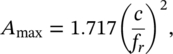
where c is the speed of sound (m/s) and fr is the resonance frequency (Hz). Therefore, if fr = 150 Hz, for example, then we cannot expect to realize more than Amax = 8.5 sabins per unit. Equation (9.24) also shows that as the resonance frequency becomes lower, more absorption can be obtained from the resonator.
EXAMPLE 9.5
A Helmholtz resonator is made of a sphere of 10 cm internal diameter. If it is to resonate at 400 Hz in air, what is the hole diameter that should be drilled into the sphere?
SOLUTION
In this case we have L = 0 and the surface of the sphere acts as a flange. Since S = πr2, from Eq. (9.23) we obtain that r = 1.7Vπ(2fr/c)2. The cavity volume can be calculated as V = 4πr3/3 = 4π(0.05)3/3 = 5.24 × 10⁻⁴ m3. Therefore, r = 1.7(5.24 × 10⁻⁴)π(2 × 400/344)2 = 1.5 cm, or 3 cm diameter.
In certain circumstances, the performance of a Helmholtz‐type resonator can be drastically influenced by the effect of its surrounding space. This is found particularly in the case for such resonators mounted in a highly absorbing plane, when interference can take place between the sound radiated from the resonator and reflected from the absorbing plane. In such circumstances special care has to be taken.
9.5.6 Perforated Panel Absorbers
As described above, single Helmholtz resonators have very selective absorption characteristics and are often expensive to construct and install. In addition, their main application lies at low frequencies. Perforated panels offer an extension to the single resonator absorber and provide a number of functional and economic advantages. When spaced away from a solid backing, a perforated panel is effectively made up of a large number of individual Helmholtz resonators, each consisting of a “neck,” constituted by the perforation of the panel, and a shared air volume formed by the total volume of air enclosed by the panel and its backing. The perforations are usually holes or slots and, as with the single resonator, porous material may be included in the airspace to introduce damping into the system. Perforated panels are mechanically durable and can be designed to provide good broadband sound absorption. The addition of a porous blanket into the airspace tends to lower the magnitude of the absorption maximum but, depending on the resistance of the material, generally broadens the effective range of the absorber [77]. At low frequencies, the perforations become somewhat acoustically transparent because of diffraction, and so the absorbing properties of the porous blanket remain almost unchanged. This is not so at high frequencies at which a reduction in the porous material absorption characteristics is observed. The resonance frequency fr for a panel perforated with holes and spaced from a rigid wall may be calculated from
(9.25)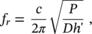
where c is the speed of sound (m/s), D is the distance from wall (m), h′ is the thickness of the panel with the end correction (m), r is the radius of hole or perforation (m), and P is the open area ratio (or perforation ratio). For a panel made up of holes of radius r metres and spaced s metres apart, the open area ratio P is given by π(r/s)2 (see Figure 9.19).
A full expression for h′ in Eq. (9.25) that takes into account the boundary layer effect is given by [78]
(9.26)
where h is the thickness of panel (m), ω is the angular frequency (rad/s), ν is the kinematic viscosity of air (15 × 10−6 m2 /s), and δ is the end correction factor. For panel hole sizes not too small we can write h′ ≈ h + 2δ r. To a first approximation the end correction factor can be assumed to be 0.85, as was done in the previous section for a single hole. However, more accurate results that include the effects of the mutual interaction between the perforations have been predicted. Table 9.2 presents some of these results.
We can see that the resonance frequency increases with the open area ratio (i.e. the number of holes per unit area) and is inversely proportional to the thickness of the panel and its distance from the solid backing.
EXAMPLE 9.6
A perforated panel with a 10% open area (P = 0.10) and thickness 6 mm is installed 15 cm in front of a solid wall. Determine the resonance frequency of the system.
SOLUTION
Assuming that the holes are not too small and if we neglect the end effect and put h′ = h + 2δr = 6 mm and D = 15 cm, then the resonance frequency fr = 560 Hz. If the percentage open area is only 1% (P = 0.01), then in the same situation, fr = 177 Hz.
In practical situations, air spaces up to 30 cm can be used with open areas ranging from 1 to 30% and thicknesses from 3 mm to 25 mm. These particular restrictions would allow a resonance frequency range of 60–4600 Hz. Many perforated panels and boards are commercially available and can readily be used to make perforated absorbers. These include: hardboards, plastic sheets, wood and plywood panels, and a variety of plane and corrugated metal facings. Some perforated sheets are available that consist of a number of different size perforations on one sheet. This can be useful to give broader absorption characteristics.
More recently, microperforated panels have been developed, which means that the diameter of the perforations is very small (less than a millimeter). In this case, the diameter is comparable to the thickness of the boundary layer, resulting in high viscous losses as air passes through the perforations and, consequently, achieving absorption without using a porous material [79, 80]. Some commercial microperforated panels take advantage of this fact, allowing the construction of a transparent absorbent device similar to a double‐glazing unit. However, obtaining broadband sound absorption using microperforated panels is difficult and requires the use of multiple layers, increasing the depth and cost of the device.
Another technique commonly used to achieve broader sound absorption characteristics is to use a variable, often wedge‐shaped, airspace behind the perforated panel [81], as shown in Figure 9.20. One of the commercial types of perforated absorber has been referenced in the literature as the “Kulihat.” [82] This is a conical absorber consisting of two or three perforated aluminum sectors held together by steel clips. The interior of the Kulihat is lined with mineral wool.
It is common practice to install a thin (1 mil to 2 mil; 1 mil = 0.0254 mm) Mylar (polyester) film or sheet behind the perforated panel to cover and protect the porous absorbing material, as shown in Figure 9.21. As long as this sheet is thin, its effect is usually only observed at high frequencies where the effective absorption can be reduced by approximately 10% of its value with no covering sheet present.
9.5.7 Slit Absorbers
The slit or slat absorber is another type of perforated resonator. These are made up of wooden battens fixed fairly closely together and spaced at some distance from a solid backing. Porous material is usually introduced into the air cavity (see Figure 9.22). This type of resonator is fairly popular with architects since it can be constructed in many different ways, offering a wide range of design alternatives. Equation (9.25) does not hold for slat absorbers since the perforations are very long. For a detailed discussion of the properties of such absorbers, the reader is advised to consult Refs. [83] and [84]. The principle of the slit resonator is, however, the same as for a general Helmholtz resonator. The resonance frequency fr (Hz) is given by the solution to the following equation:
(9.27)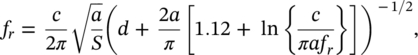
where c is the speed of sound (m/s), a is the slit width (m), d is the slit depth (m), and S is the cross‐sectional area (m2) of space behind the slats formed by each slat (i.e. slat width W × air space D). A typical acoustical design procedure would be to choose a resonance frequency fr and a slat of width W and thickness d and then determine the required value of air space from S = W × D for a chosen value of slit width a.
EXAMPLE 9.7
Design a slit resonator having fr = 200 Hz and with the resonator constructed with slats measuring 25 × 84 mm.
SOLUTION
We have W = 84 mm and d = 25 mm. Since the slit width should be approximately 10–20% the width of the slat, let us try a slat spacing (i.e. slit width) of 8 mm. Then, all the known values in Eq. (9.27) are fr = 200 Hz, W = 0.084 m, d = 0.025 m, a = 0.008 m, and c = 343 m/s. Equation (9.27) can be rewritten by multiplying and dividing both sides of the equation by ![]() and fr, respectively. Then, S can be obtained by squaring both sides of the resulting equation. Replacing the known values gives S = 0.01 m2 and since W = 0.084 m, we require D = 0.13 m.
and fr, respectively. Then, S can be obtained by squaring both sides of the resulting equation. Replacing the known values gives S = 0.01 m2 and since W = 0.084 m, we require D = 0.13 m.
We see, therefore, that for the above example of a slit resonator, an air space of 13 cm is required to provide a resonance frequency of 200 Hz. If the calculation is repeated for a 100‐Hz resonance frequency, it is found that an air space of some 48 cm is required.
9.5.8 Suspended Absorbers
This class of sound absorbers is known by several names including suspended absorbers, functional absorbers, and space absorbers. They generally refer to sound‐absorbing objects and surfaces that can be easily suspended, either as single units or as a group of single units within a room. They are particularly useful in rooms in which it is difficult to find enough surface area to attach conventional acoustical absorbing materials either through simple lack of available space or interference from other objects or mechanical services such as ducts and pipes, in the ceiling space (see Figure 9.23). It is relatively easy and inexpensive to install them, without interfering with existing equipment. For this reason they are often used in noisy industrial installations such as assembly rooms or machine shops. An advantage of flat suspended panels is that they absorb sound on both sides.
Functional absorbers are usually made from highly absorbing materials in the form of a variety of three‐dimensional shapes, such as spheres, cones, double cones, cubes, and panels. These are usually filled with a porous absorbing material. Since sound waves fall on all their surfaces and because of diffraction, they are able to yield high values of effective absorption coefficients. It is, however, more usual to describe their absorption characteristics in terms of their total absorption in sabins per unit, as a function of octave band frequencies, rather than to assign an absorption coefficient to their surfaces. One also finds that when a group of functional absorbers are installed, the total absorption realized from the group depends upon the spacing between the individual units to a certain extent. Once a certain optimum spacing has been reached the effective absorption per unit does not increase [85, 86].
9.5.9 Acoustical Spray‐on Materials
Acoustical spray‐on materials consist of a range of materials formed from mineral or synthetic organic fibers mixed with a binding agent. This holds the fibrous content together in a porous manner and also acts as an adhesive. During the spraying application, the fibrous material is mixed with a binding agent and water to produce a soft lightweight material of coarse surface texture with high sound‐absorbing characteristics. Due to the nature of the binding agent used, the material may be easily applied directly to a wide number of surface types including wood, concrete, metal lath, steel, and galvanized metal. When sprayed onto a solid backing, this type of spray‐on material usually exhibits good mid‐ and high‐frequency sound absorption and when applied to, for example, metal lath with an airspace behind it, the material then exhibits good low‐frequency absorption as well. As would be expected from previous discussions of porous absorbers, the absorption values increase with greater depth of application, especially at low frequencies. Spray‐on depths of up to 5 cm are fairly common [59].
The sound absorption characteristics of such materials are very much dependent upon the amount and type of binding agent used and the way it is mixed during the spray‐on process. If too much binder is used, then the material becomes too hard and therefore a poor absorber, while on the other hand, if too little binder is employed, the material will be prone to disintegration; and, since it will have a very low flow resistance, it will also not be a good absorber [4]. Some products use two binders. One is impregnated into the fibrous material during manufacture, while the other is in liquid form and included during application. The fibrous material (containing its own adhesive) and the liquid adhesive are applied simultaneously to the surface using a special nozzle. The material is particularly resistant to disintegration or shrinkage and, furthermore, is fire‐resistant and possesses excellent thermal insulation properties.
If visually acceptable, spray‐on materials of this type can be successfully used as good broadband absorbing materials in a variety of architectural spaces including schools, gymnasiums, auditoriums, shopping centers, pools, sports stadiums, and in a variety of industrial applications such as machine shops and power plants. Disadvantages generally include the difficulty to clean and redecorate the material, although some manufacturers claim that their product can be spray‐painted without loss of acoustical performance. The data for such claims should be checked carefully before one proceeds to the painting of a surface.
9.5.10 Acoustical Plaster
The term acoustical plaster has been applied to a number of combinations of vermiculite and binder agents such as gypsum or lime. They are usually applied either to a plaster base or to concrete and must have a solid backing. Because of this, acoustical plasters have poor low‐frequency sound absorption characteristics (also due to the thickness of application, which rarely exceeds 13 mm). This can be slightly improved by application to metal lath. The material may be applied by a hand trowel or by machine. However, the latter tends to compact the material and give lower sound absorption characteristics. The surface of acoustical plasters can be sprayed with water‐thinned emulsion paint without any significant loss of absorption, although brushed oil‐based paints should never be used. Figure 9.24 shows typical sound absorption characteristics for a 13‐mm‐thick hand trowel applied acoustical plaster taken from a variety of published manufacturer’s data [4].
9.5.11 Measurement of Sound Absorption Coefficients
Although some approximate values for sound absorption coefficients and resonance frequency characteristics can be estimated from the geometry, flow resistance, porosity, and other physical factors, it is clearly necessary to have actual measured values of absorption coefficients for a variety of materials and different constructions. There are two standardized methods to measure the sound absorption coefficient: using either a reverberation room or using an impedance tube [60, 87–90].
Tables of absorption coefficients are published for a variety of acoustical materials in which numerous mounting systems are employed. Sound absorption coefficients and corresponding values of NRC of some common sound‐absorbing materials and construction materials are shown in Table 9.3. More extensive tables of sound absorption coefficients of materials can be found in the literature. The book by Trevor Cox provides a good review on sound‐absorbing materials [91]. The tables are very often made up after receiving absorption results from a number of independent testing laboratories for the same sample of material. It is found that even when all of the requirements of either the International Organization for Standardization (ISO) or ASTM standards are met, there can still be quite large differences observed between the values obtained for the absorption coefficients measured in different laboratories for the same sample. These differences can be due to variations in the diffuseness of the testing rooms and to human error and bias in measuring the reverberation times.
Table 9.3 Sound absorption coefficient α(f) and corresponding NRC of common materials [60].
| Material | Frequency (Hz) | ||||||
|---|---|---|---|---|---|---|---|
| 125 | 250 | 500 | 1000 | 2000 | 4000 | NRC | |
| Fibrous glass (typically 64 kg/m3) hard backing | |||||||
| 25 mm thick | 0.07 | 0.23 | 0.48 | 0.83 | 0.88 | 0.80 | 0.61 |
| 50 mm thick | 0.20 | 0.55 | 0.89 | 0.97 | 0.83 | 0.79 | 0.81 |
| 10 cm thick | 0.39 | 0.91 | 0.99 | 0.97 | 0.94 | 0.89 | 0.95 |
| Polyurethane foam (open cell) | |||||||
| 6 mm thick | 0.05 | 0.07 | 0.10 | 0.20 | 0.45 | 0.81 | 0.21 |
| 12 mm thick | 0.05 | 0.12 | 0.25 | 0.57 | 0.89 | 0.98 | 0.46 |
| 25 mm thick | 0.14 | 0.30 | 0.63 | 0.91 | 0.98 | 0.91 | 0.71 |
| 50 mm thick | 0.35 | 0.51 | 0.82 | 0.98 | 0.97 | 0.95 | 0.82 |
| Hair felt | |||||||
| 12 mm thick | 0.05 | 0.07 | 0.29 | 0.63 | 0.83 | 0.87 | 0.46 |
| 25 mm thick | 0.06 | 0.31 | 0.80 | 0.88 | 0.87 | 0.87 | 0.72 |
| Brick | |||||||
| Unglazed | 0.03 | 0.03 | 0.03 | 0.04 | 0.04 | 0.05 | 0.04 |
| Painted | 0.01 | 0.01 | 0.02 | 0.02 | 0.02 | 0.02 | 0.02 |
| Concrete block, painted | 0.01 | 0.05 | 0.06 | 0.07 | 0.09 | 0.03 | 0.07 |
| Concrete | 0.01 | 0.01 | 0.02 | 0.02 | 0.02 | 0.02 | 0.02 |
| Wood | 0.15 | 0.11 | 0.10 | 0.07 | 0.06 | 0.07 | 0.09 |
| Glass | 0.35 | 0.25 | 0.18 | 0.12 | 0.08 | 0.04 | 0.16 |
| Gypsum board | 0.29 | 0.10 | 0.05 | 0.04 | 0.07 | 0.09 | 0.07 |
| Plywood, 10 mm | 0.28 | 0.22 | 0.17 | 0.09 | 0.10 | 0.11 | 0.15 |
| Soundblox concrete block | |||||||
| Type A (slotted), 15 cm (6 in.) | 0.62 | 0.84 | 0.36 | 0.43 | 0.27 | 0.50 | 0.48 |
| Type B, 15 cm (6 in.) | 0.31 | 0.97 | 0.56 | 0.47 | 0.51 | 0.53 | 0.63 |
| Spray‐acoustical (on gypsum wall board) | 0.15 | 0.47 | 0.88 | 0.92 | 0.87 | 0.88 | 0.79 |
| Acoustical plaster (25 mm thick) | 0.25 | 0.45 | 0.78 | 0.92 | 0.89 | 0.87 | 0.76 |
| Carpet | |||||||
| On foam rubber | 0.08 | 0.24 | 0.57 | 0.69 | 0.71 | 0.73 | 0.55 |
| On concrete | 0.02 | 0.06 | 0.14 | 0.37 | 0.60 | 0.66 | 0.29 |
The main applications of sound‐absorbing materials in noise control are [11, 92]: (i) incorporation in noise control enclosures, covers, and wrappings to reduce reverberant build‐up of sound and hence increase insertion loss, (ii) incorporation in flow ducts to attenuate sound from fans and flow control devices, (iii) application to the surfaces of rooms to control reflected sound (e.g. to reduce steady‐state sound pressure levels in reverberant fields), (iv) in vehicles (walls, engine compartments, and engine exhausts), (v) in lightweight walls and ceilings of buildings, and (vi) on traffic noise barriers to suppress reflections between the side of the vehicle and the barrier or to increase barrier performance by the presence of absorbent on and around the top of the barrier.
However, sound‐absorbing materials are most commonly used to optimize the reverberation time in rooms and to reduce the sound pressure level in reverberant fields. These applications will now be described separately.
9.5.12 Optimization of the Reverberation Time
When sound is introduced into a room, the reverberant field level will increase until the rate of sound energy input is just equal to the rate of sound energy absorption. If the sound source is abruptly turned off, the reverberant field will decay at a rate determined by the rate of sound energy absorption.
As mentioned before, the reverberation time of a room depends upon the sound absorption present within it. In addition, the reverberation time has become recognized as the most important single parameter used to describe the acoustical performance of auditoriums. Changes in the total absorption can be made by modifying the values of areas and sound absorption coefficients of the room surfaces. Therefore, it is possible to change the values of reverberation time to provide performers and listeners with a high degree of intelligibility throughout the room and optimum sound enrichment.
In a room, for speech to be understood fully, each component of the speech must be heard by the listener. If the room has a long reverberation time, then the speech components overlap and a loss of intelligibility results. Similarly, for music enjoyment and appreciation, a certain amount of reverberation is required to obtain the quality and blend of the music. It is, however, much more difficult to describe the acoustical qualities of a room used for music since many are subjective and therefore cannot be described in measurable physical quantities. Optimum reverberation times are not only required for good subjective reception but also for efficient performances.
Optimum values of the reverberation time for various uses of a room may be calculated approximately by [93]
(9.28)![]()
where TR is the reverberation time (s), V is the room volume (m3), and K is a constant that takes the following values according to the proposed use: For speech K = 4, for orchestra K = 5, and for choirs and rock bands K = 6. It has been suggested that, at frequencies in the 250‐Hz octave band and lower frequencies, an increase is needed over the value calculated by Eq. (9.28), ranging from 40% at 250 Hz to 100% at 63 Hz. Other authors have suggested optimum TR values for rooms for various purposes [14, 62].
However, achieving the optimum reverberation time for a room may not necessarily lead to good speech intelligibility or music appreciation. It is essential to adhere strictly to the other design rules for shape, volume, and time of arrival of early reflections [94, 95].
EXAMPLE 9.8
Consider an auditorium of dimensions 15 m × 20 m × 4 m, with an average Sabine absorption coefficient ![]() = 0.24 for the whole room surface at 500 Hz. Is this room appropriate to be used as an auditorium?
= 0.24 for the whole room surface at 500 Hz. Is this room appropriate to be used as an auditorium?
SOLUTION
The total surface area of the room is calculated as S = 2(20 × 4 + 15 × 4 + 15 × 20) = 880 m2 and its volume is V = 1200 m3. Assuming that there is a uniform distribution of absorption throughout the room, the reverberation time can be obtained as given by Sabine TR = 0.161 V/(S ![]() ) = (0.161 × 1200)/(880 × 0.24) = 0.9 s. Now substituting the value of room volume in Eq. (9.28), and considering K = 4 for using the room for speech, we obtain TR = 0.9 s. Therefore, the total absorption of such a room is optimum for its use as an auditorium, at least at 500 Hz. This calculation may be repeated at each frequency for which absorption coefficient data are available.
) = (0.161 × 1200)/(880 × 0.24) = 0.9 s. Now substituting the value of room volume in Eq. (9.28), and considering K = 4 for using the room for speech, we obtain TR = 0.9 s. Therefore, the total absorption of such a room is optimum for its use as an auditorium, at least at 500 Hz. This calculation may be repeated at each frequency for which absorption coefficient data are available.
9.5.13 Reduction of the Sound Pressure Level in Reverberant Fields
When a machine is operated inside a building, the machine operator usually receives most sound through a direct path, while people situated at greater distances receive sound mostly through reflections (see Figure 9.11).
In the case of machinery used in reverberant spaces such as factory buildings, the reduction in sound pressure level Lp in the reverberant field caused by the addition of sound‐absorbing material, placed on the walls or under the roof (see Figure 9.23), can be estimated for a source of sound power level LW from the so‐called room equation:
(9.29)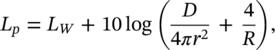
where the room constant R = S ![]() /(1−
/(1−![]() ),
), ![]() is the surface average absorption coefficient of the walls, D is the source directivity, and r is the distance in metres from the source. The surface average absorption coefficient
is the surface average absorption coefficient of the walls, D is the source directivity, and r is the distance in metres from the source. The surface average absorption coefficient ![]() may be estimated from
may be estimated from
(9.30)![]()
where S1, S2, S3, … are the surface areas of material with absorption coefficients α1, α2, α3, …, respectively. For the suspended absorbing panels shown in Figure 9.23, both sides of the panel are normally included in the surface area calculation. If the sound absorption is increased, then from Eq. (9.29) the change in sound pressure level ΔL in the reverberant space (beyond the critical distance rc) is
(9.31)![]()
If ![]() ≪ 1, then the reduction in sound pressure level (sometimes called the noise reduction) is given by
≪ 1, then the reduction in sound pressure level (sometimes called the noise reduction) is given by
(9.32)![]()
where S2 is the total surface area of the room walls, floor, and ceiling and any suspended sound‐absorbing material, ![]() is the average sound absorption coefficient of these surfaces after the addition of sound‐absorbing material, and S1 and
is the average sound absorption coefficient of these surfaces after the addition of sound‐absorbing material, and S1 and ![]() are the area and the average sound absorption coefficient before the addition of the material.
are the area and the average sound absorption coefficient before the addition of the material.
EXAMPLE 9.9
A machine source operates in a building of dimensions 30 m × 30 m with a height of 10 m. Suppose the average absorption coefficient is ![]() = 0.02 at 1000 Hz. What would be the noise reduction in the reverberant field if 100 sound‐absorbing panels with dimensions 1 m × 2 m each with an absorption coefficient of
= 0.02 at 1000 Hz. What would be the noise reduction in the reverberant field if 100 sound‐absorbing panels with dimensions 1 m × 2 m each with an absorption coefficient of ![]() = 0.8 at 1000 Hz were suspended from the ceiling (assume both sides absorb sound)?
= 0.8 at 1000 Hz were suspended from the ceiling (assume both sides absorb sound)?
SOLUTION
The room surface area = 2(900) + 4(300) = 3000 m2, therefore R1 = (3000 × 0.02)/0.98 = 60/0.98 = 61.2 sabins (m2). The new average absorption coefficient ![]() = (3000 × 0.02 + 200 × 2 × 0.8)/3400 = 0.11. The new room constant is (3400 × 0.11)/0.89 = 420 sabins (m2 ). Thus from Eq. (9.31) the predicted noise reduction ΔL = 10 log(420/61.2) = 8.4 dB. This calculation may be repeated at each frequency for which absorption coefficient data are available. It is normal to assume that about 10 dB is the practical limit for the noise reduction that can be achieved by adding sound‐absorbing material in industrial situations.
= (3000 × 0.02 + 200 × 2 × 0.8)/3400 = 0.11. The new room constant is (3400 × 0.11)/0.89 = 420 sabins (m2 ). Thus from Eq. (9.31) the predicted noise reduction ΔL = 10 log(420/61.2) = 8.4 dB. This calculation may be repeated at each frequency for which absorption coefficient data are available. It is normal to assume that about 10 dB is the practical limit for the noise reduction that can be achieved by adding sound‐absorbing material in industrial situations.
Leave a Reply