Vibration isolation has been discussed frequently in the literature [50]. Vibration isolators are used in two main situations: (i) where a machine source is producing vibration and it is desired to prevent vibration energy flowing to supporting structures and (ii) where a delicate piece of equipment (such as an electronics package or precision grinder) must be protected from vibration in the structure. It is the first case that will receive attention here. Primary emphasis is placed on reducing the force transmitted from the machine source to the supporting structure, but a secondary consideration is to reduce the vibration of the machine source itself.
It is often found that machines are attached to metal decks, grills, and sometimes lightweight wood or concrete floors. The machine on its own is usually incapable of radiating much noise (particularly at low frequency). The supporting decks, grills, and floors, however, tend to act like sounding boards, just as in musical instruments, and amplify the machine noise. Properly designed vibration isolators can overcome this noise problem.
Vibration isolators are of three main types: (i) spring, (ii) elastomeric, and (iii) pneumatic. Spring isolators are durable but have little damping. Elastomeric isolators are less durable and are subject to degradation due to corrosive environments. They have higher damping and are less expensive. Pneumatic isolators are used where very low frequency excitation is present.
Often the exciting forces are caused by rotational out‐of‐balance forces in machines or machine elements or by magnetic or friction effects. Usually, these forces are simple harmonic in character. Such forces occur in electric motors, internal combustion engines, bearings, gears, and fans. Sometimes, however, the exciting forces may be impulsive in nature (e.g. in the case of punch presses, stamping operations, guillotines, tumblers, and any machines where impacts occur). The design of vibration isolators for a machine under the excitation of a simple harmonic force is considered below.
9.3.1 Theory of Vibration Isolation
A machine may be considered, for simplicity, to be represented by a rigid mass m. If the machine is attached directly to a large rigid massive floor, as shown in Figure 9.4, then all the periodic force Fm(t) applied to the mass is directly transmitted to the floor. We will assume that the force on the mass is vertical and Fm(t) = Fm sin 2πf t, where Fm is the amplitude of this force, and f is its frequency (Hz). If a vibration isolator is now placed between the machine and the floor, we can model this system with the well‐known single‐degree‐of‐freedom system shown in Figure 9.5. The following discussion assumes that the isolators have a constant stiffness and that the damping is viscous in nature. Suppose, for the moment, that the periodic force is stopped and that the mass m is brought to rest. If the mass m is displaced from its equilibrium position and released, then it will vibrate with a natural frequency of vibration fn given by
(9.1)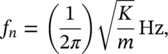
where, in International System (SI) units, K is the stiffness (N/m) and m is the mass (kg). (see Chapter 2 of this book.)
If the exciting force Fm(t) is now resumed, then a force Ft(t) will be transmitted to the rigid floor. This force Ft(t) will be out of phase with Fm(t), but it is simple to show that the ratio of the amplitudes of the forces in the steady state is given by
(9.2)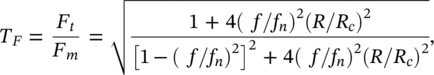
where f is the frequency of the exciting force (Hz), fn is the natural frequency of vibration of the mass m supported by the spring (Hz), R is the coefficient of damping (Ns/m), and Rc is the coefficient of critical damping (![]() ). See Chapter 2 of this book for further discussion on vibration. The ratio Ft /Fm is known as the force transmissibility TF.
). See Chapter 2 of this book for further discussion on vibration. The ratio Ft /Fm is known as the force transmissibility TF.
The vibration amplitude A of the machine mass m is given by
(9.3)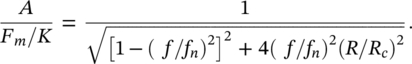
The ratio A/(Fm /K) is known as the dynamic magnification factor (DMF). This is because Fm /K represents the static displacement of the mass m if a static force of value Fm is applied, while A represents the dynamic displacement amplitude that occurs due to the periodic force of amplitude Fm. Note that the ratio R/Rc is known as the damping ratio δ. If δ = 1.0, the damping is called critical damping. With most practical vibration isolators, δ may be in the range from about 0.01 to 0.2. Equations (9.2) and (9.3) are plotted in Figures 2.9 and 2.10, respectively.
If the machine is run at the natural frequency fn, we see from Figure 2.9 that f/fn is 1.0 and the force amplitude transmitted to the floor is very large, particularly if the damping in the isolator support is small. If the machine is operated much above the natural frequency, however, then the force amplitude transmitted to the floor will be very small.
We define the efficiency η of the isolator as
(9.4)![]()
EXAMPLE 9.1
Suppose we wish to isolate the 120‐Hz vibration of an electric motor so that the system has a natural frequency of 12 Hz. Calculate a) the force transmissibility and b) the isolator efficiency of the resulting system.
SOLUTION
If we choose isolators so that the system has a natural frequency of 12 Hz, then the ratio f/fn = 10. If the damping in the isolator system is R/Rc = 0.1, the force transmissibility will be only about 0.025, or 2.5% (see Figure 2.10). Thus the isolator efficiency is 97.5%. To reduce the force transmissibility still further, we could use softer isolators and choose a still lower resonance frequency. There is some danger in doing this, however, because the static deflection of the machine will naturally increase if we use softer isolators. Since a large static deflection may be undesirable (it may interfere with the operation of the machine), this restricts the softness of the isolator and thus how low we can make the natural frequency fn. The static deflection d produced in the isolator by the gravity force on the mass m is given by d = mg/K.
We have already seen that the natural frequency is related to K and m by ![]() . Hence we can relate the static deflection d to the natural frequency fn:
. Hence we can relate the static deflection d to the natural frequency fn:
(9.5)![]()
where the static deflection d is given in centimetres (or inches) and g is the acceleration of gravity, 981 cm/s2. The relationship given in Eq. (9.5) has been plotted in Figure 9.6. The greatest static deflection d that can be allowed from operational considerations should be chosen. This will then allow a determination of the lowest allowable fn. It should be noted that excessive static deflection may interfere with the operation of the machine by causing alignment problems. Also, using isolators with a small vertical stiffness usually means that they may have a small horizontal stiffness, and there can be stability problems. Both these considerations limit the lowest allowable fn.
With springs, the damping is small (usually δ < 0.1), and we may use Eqs. (9.2) and (9.3) and Figures 2.9 and 2.10, assuming that δ = 0. With δ = 0 (or, equivalently, R = 0), Eqs. (9.2) and (9.5) give
(9.6)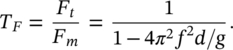
This result is plotted in Figure 9.7. The suggested procedure is as follows.
- Establish the total weight of the machine and the lowest forcing frequency experienced.
- From Figure 9.7 select the force transmissibility allowable (this determines the static deflection, given the lowest forcing frequency.
- From the spring constants given by the manufacturer, the machine weight, and the static deflection, choose the appropriate vibration isolator.
EXAMPLE 9.2
An electric motor of mass 100 kg and a reciprocating compressor of mass 500 kg are mounted on a common support. The motor runs at 2400 revolutions/minute (rpm) and by a belt drives the compressor at 3000 rpm. The vertical force fed to the support is thought to be excessive. Choose six equal spring mounts to provide a force transmissibility not exceeding 5%.
SOLUTION
- The total machine weight is 600 kg, and the lowest forcing frequency is 2400 rpm (or 40 Hz).
- From Figure 9.7, the static deflection required is 0.33 cm (0.13 in.).
- Thus, since there are six spring isolators, each must support a mass of 100 kg. This requires a spring constant for each isolator of 981/0.33 = 3000 N/cm.
As a check on the calculation, we see from Figure 9.6 that a static deflection of 0.33 cm. requires a natural frequency of about 8.6 Hz. Thus, the ratio of forcing frequency to natural frequency f/fn = 40/8.6 = 4.65. From Figure 2.10, with zero damping, TF = 0.05, which agrees with the design requirement.
9.3.2 Machine Vibration
There are several other factors that should be considered in isolator design. First, we notice from Figures 2.9 and 2.10 that when a machine is started or stopped, it will run through the resonance condition and then, momentarily, f/fn = 1. When passing through the resonance condition, large vibration amplitudes can exist on the machine, and the force transmitted will be large, particularly if the damping is small. Assuming viscous damping, to provide small force transmissibility at the operating speed, small damping is required; however, to prevent excessive machine vibration and force transmission during stopping and starting, large damping is needed. These two requirements are conflicting. Fortunately, some forces, such as out‐of‐balance forces, are much reduced during starting and stopping. However, it is normal to provide a reasonable amount of damping (δ = 0.1–0.2) in spring systems to reduce these starting and stopping problems. The severity of the machine vibration problem can be gauged from Figure 9.8.
9.3.3 Use of Inertia Blocks
Inertia blocks are normally made from concrete poured onto a steel frame. If the mass supported by the vibration isolators is increased by mounting a machine on an inertia block, the static deflection will be increased. If the isolator stiffness is correspondingly increased to keep the static deflection the same, then there is no change in the system’s natural frequency or the force transmissibility TF. The use of an inertia block does, however, result in reduced vibration amplitude of the machine mass. It also has additional advantages including (i) improving stability by providing vibration isolator support points that are farther apart, (ii) lowering the center of gravity of the system, thus improving stability and reducing the effect of coupled modes and rocking natural frequencies, (iii) producing more even weight distribution for machines often enabling the use of symmetrical vibration isolation mounts, (iv) functioning as a local acoustical barrier to shield the floor of an equipment room from the noise radiated from the bottom of the machine and reducing its transmission to rooms below, and (v) reducing the effect on the machine of external forces such as transient loads or torques caused by operation of motors or fans or rapid changes in machine load or speed.
9.3.4 Other Considerations
The performance of vibration isolators in the high‐frequency range (f/fn ≥ 1) is often disappointing. There are several possible reasons; but often they all result in an increase in force transmissibility TF for f/fn ≥ 1. Usually, the reasons are deviations from the simple single‐degree‐of‐freedom model as mentioned below [5].
a) Support Flexibility
If the assumption that the support is rigid does not hold, then the support will also deflect (e.g. because of floor flexibility). If the isolator stiffness is similar in magnitude to that of the supporting floor, then additional resonances in the floor–machine system will occur for f/fn > 1. It is normal practice to choose isolators (assuming a rigid support or floor) to have a natural frequency well below the fundamental natural frequency of the floor itself. (If possible there should not be any machine‐exciting frequencies in the frequency range 0.8–1.3 times the floor fundamental natural frequency.) The fundamental natural frequency of a wood floor is usually in the 20–30 Hz frequency range, while that of a concrete floor is in the 30–100 Hz range.
b) Machine Resonances
Internal resonances in the machine structure will also increase the force transmissibility TF in a similar manner to support flexibility. Increasing the stiffness and/or the damping of machine members can help to reduce this effect.
c) Standing‐Wave Effects
Standing‐wave effects in the vibration isolators can significantly decrease their performance and increase force transmissibility for f/fn ≥ 1, but this typically occurs only at high frequency. This effect can be reduced by increasing the damping in the isolators. Springs particularly suffer from this problem because of their low inherent damping. Soft materials (such as felt or rubber) placed between the spring and the support can alleviate the problem. In elastometric isolators the effects of standing wave resonances are small because of their higher damping.
d) Shock Isolation
If the forces in the machine are impulsive in character (such as caused by repeated impacts), then the discussion for isolation of the single degree‐of‐freedom model presented so far can still be used. It is normal practice to choose an isolator that provides a natural period T (T = 1/fn), which is much greater than the shock pulse duration but less than the period of repetition of the force.
EXAMPLE 9.3
A nail‐making machine cuts nails five times each second (T = 0.2 second). The shock pulse duration is approximately 0.015 second. What is a suitable choice of vibration isolator for the machine?
SOLUTION
Elastometric isolators that provide a natural period of vibration of 0.1 second (natural frequency of 10 Hz) would be a good choice. They have high damping. An elastomer is a type of viscoelastic damping material. In the following section the use of damping materials will be discussed.
Leave a Reply