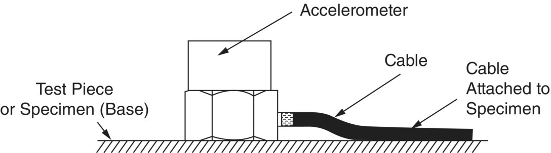
Piezoelectric accelerometers produce some output signal when subjected to acoustic signals or base strains. Normally, the acoustic sensitivity is low (producing an apparent acceleration of smaller than 1 g for a sound pressure level of 160 dB). As the test object vibrates, it will induce strain in the accelerometer base with a consequent output signal. Most accelerometer bases are made thick and rigid to reduce this effect. As was discussed in Section 7.5.2, all accelerometers exhibit a fundamental resonance frequency [4] and the upper frequency limit is extended in some accelerometer designs by using high damping. However, it should be noted that poor mounting techniques can have a marked effect on the frequency response above 2000 or 3000 Hz. Below this frequency, the mounting technique is not important as long as the accelerometer is fixed directly onto the specimen. The best technique is to attach the accelerometer to the specimen with a threaded steel stud. When this mounting method cannot be used, cement is also acceptable, and wax can be used with small to medium‐sized accelerometers (up to 20–30 g) [25]. At low frequencies, magnets may be used. Ground loops must be avoided, in particular, when low acceleration levels are measured. With higher acceleration levels, ground loops can also cause problems. Measurement errors of 50% or more may be caused by ground loops with acceleration amplitudes of 100 m/s2 or more. In such cases the accelerometer should be electrically isolated from the specimen and attached with a nonconducting stud or cemented to a mica washer, which is in turn cemented to the specimen. Cable “whip” can produce electrical noise, and cables should be attached to the specimen as shown in Figure 7.15.
In the case of the measurement of high‐frequency vibration of thin metal plates, considerable care should be taken when using an accelerometer because of the mass loading effect. Well below its resonance frequency, the accelerometer can be assumed to act as a pure mass. The velocity of the test piece u0 can be assumed to be reduced to u1 by the addition of the accelerometer [28]
(7.13)![]()
where Z = mechanical impedance of test piece at the attachment point, ω = angular frequency, and m is the accelerometer mass. The input point impedance for a metal plate can be assumed to be
(7.14)![]()
where ρ = plate density, cL = longitudinal wave speed in plate, and h = plate thickness. Substituting Eqs. (7.14) in (7.13) and assuming |Z| = |jωm|, which gives a 3‐dB reduction in velocity amplitude (from Eq. (7.13)), gives the frequency f3dB at which the 3‐dB reduction occurs as
(7.15)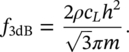
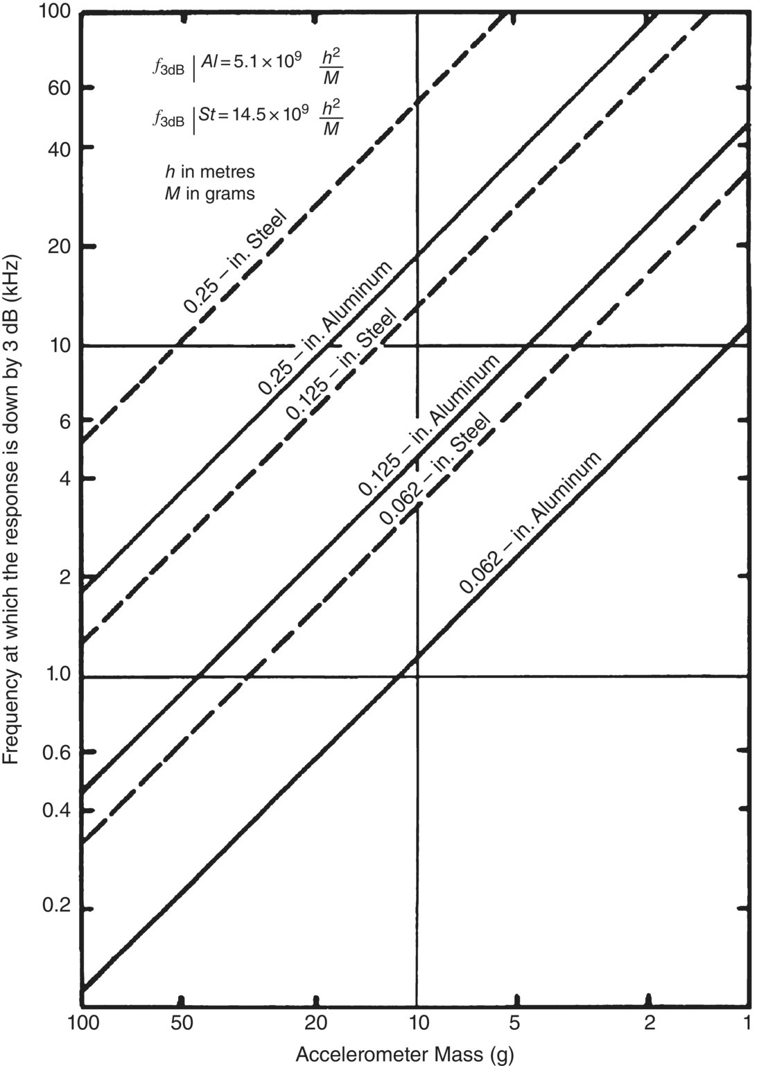
Equation (7.15) is plotted in Figure 7.16. This figure suggests that even lightweight accelerometers will “load” thin metal plates (e.g. a 10‐g accelerometer will mass “load” a 3.2‐mm [1/8‐in.] aluminum plate at frequencies above about 4000 Hz). A general rule is to ensure that the accelerometer mass is less than one tenth of the mass of the structure [25].
To overcome such mass loading problems, various types of noncontacting gauges have been produced and still are widely used. Particular examples of where noncontacting gauges are invaluable are in the study of the vibration of thin sandwich composite panels and of loudspeaker cones. Examples of noncontacting gauges are given in Ref. [4].
EXAMPLE 7.8
An accelerometer is placed on an aluminum plate of thickness 3 mm. It is required that the frequency at which the response is down by 3‐dB be below 9 kHz. Determine the appropriate mass of the accelerometer to comply with this requirement.
SOLUTION
The values of density and longitudinal wave speed in aluminum are ρ = 2700 kg/m3 and cL = 5200 m/s, respectively. Using Eq. (7.15) we find the required mass
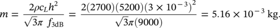
Therefore, the mass of the accelerometer must be less than 5‐g to obtain a good measure of the plate vibration.
Leave a Reply