Standing‐wave phenomena are observed in many situations in acoustics and the vibration of strings and elastic structures. Thus they are of interest with almost all musical instruments (both wind and stringed) (see Part XIV in the Encyclopedia of Acoustics [19]); in architectural spaces such as auditoria and reverberation rooms; in volumes such as automobile and aircraft cabins; and in numerous cases of vibrating structures, from tuning forks, xylophone bars, bells and cymbals to windows, wall panels, and innumerable other engineering systems including aircraft, vehicle, and ship structural members. With each standing wave is associated a mode shape (or shape of vibration) and an eigen (or natural) frequency. Some of these systems can be idealized as simple one‐, two‐, or three‐dimensional systems. For example, with a simple wind instrument such as a flute, Eq. (3.1) together with the appropriate spatial boundary conditions can be used to predict the predominant frequency of the sound produced. Similarly, the vibration of a string on a violin can be predicted with an equation identical to Eq. (3.1) but with the variable p replaced by the lateral string displacement. With such a string, solutions can be obtained for the fundamental and higher natural frequencies (overtones) and the associated standing wave mode shapes (which are normally sine shapes). In such a case for a string with fixed ends, the so‐called overtones are just integer multiples (2, 3, 4, 5, …) of the fundamental frequency.
The standing wave with the flute and string can be considered mathematically to be composed of two waves of equal amplitude traveling in opposite directions. Consider the case of a lateral wave on a string under tension. If we create a wave at one end, it will travel forward to the other end. If this end is fixed, it will be reflected. The original (incident) and reflected waves interact (and if the reflection is equal in strength) a perfect standing wave will be created. In Figure 3.30 we show three different frequency waves that have interacted to cause standing waves of different frequencies on the string under tension. A similar situation can be conceived to exist for one‐dimensional sound waves in a tube or duct. If the tube has two hard ends, we can create similar standing one‐dimensional sound waves in the tube at different frequencies. In a tube, the regions of high sound pressure normally occur at the hard ends of the tube, as shown in Figure 3.31. See Refs. [14, 32, 33].
A similar situation occurs for bending waves on bars, but because the equation of motion is different (dispersive), the higher natural frequencies are not related by simple integers. However, for the case of a beam with simply supported ends, the higher natural frequencies are given by 22, 32, 42, 52, …, or 4, 9, 16, 25 times the fundamental frequency, …, and the mode shapes are sine shapes again.
The standing waves on two‐dimensional systems (such as bending vibrations of plates) may be considered mathematically to be composed of four opposite traveling waves. For simply supported rectangular plates the mode shapes are sine shapes in each direction. For three‐dimensional systems such as the air volumes of rectangular rooms, the standing waves may be considered to be made up of eight traveling waves. For a hard‐walled room, the sound pressure has a cosine mode shape with the maximum pressure at the walls, and the particle velocity has a sine mode shape with zero normal particle velocity at the walls. See chapter 6 in the Handbook of Acoustics [1] for the natural frequencies and mode shapes for a large number of acoustical and structural systems.
For a three‐dimensional room, normally there are standing waves in three directions with sound pressure maxima at the hard walls.
To understand the sound propagation in a room, it is best to use the three‐dimensional wave equation in Cartesian coordinates:
(3.86)![]()
or
(3.87)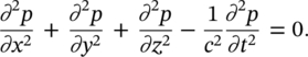
This equation can have solutions that are “random” in time or are for the special case of a pure‐tone, “simple harmonic.”
The simple harmonic solution is of considerable interest to us because we find that in rooms there are solutions only at certain frequencies. It may be of some importance now to mention both the sinusoidal solution and the equivalent solution using complex notation that is very frequently used in acoustics and vibration theory.
For a one‐dimensional wave, the simple harmonic solution to the wave equation is
(3.88)![]()
where k = ω/c = 2πf/c (the wavenumber).
The first term in Eq. (3.88) represents a wave of amplitude ![]() traveling in the +x‐direction. The second term in Eq. (3.88) represents a wave of amplitude
traveling in the +x‐direction. The second term in Eq. (3.88) represents a wave of amplitude ![]() traveling in the −x‐direction.
traveling in the −x‐direction.
The equivalent expression to Eq. (3.88) using complex notation is
(3.89)![]()
where ![]() , Re{} means real part; and
, Re{} means real part; and ![]() and
and ![]() are complex amplitudes of the sound pressure; remember k = ω/c; kc = 2πf. Both Eqs. (3.88) and (3.89) are solutions to Eq. (3.86).
are complex amplitudes of the sound pressure; remember k = ω/c; kc = 2πf. Both Eqs. (3.88) and (3.89) are solutions to Eq. (3.86).
For the three‐dimensional case (x, y, and z propagation), the sinusoidal (pure tone) solution to Eq. (3.87) is
(3.90)![]()
Note that there are 23 (eight) possible solutions given by Eq. (3.90). Substitution of Eq. (3.90) into Eq. (3.87) (the three‐dimensional wave equation) gives (from any of the eight (23) equations):
(3.91)![]()
from which the wavenumber k is
(3.92)![]()
and the so‐called direction cosines with the x, y and z directions are cos θx = ±kx /k, cos θy = ±ky /k, and cos θz = ±kz /k (see Figure 3.32).
Equations (3.91) and (3.92) apply to the cases where the waves propagate in unbounded space (infinite space) or finite space (e.g. rectangular rooms).
For the case of rectangular rooms with hard walls, we find that the sound (particle) velocity perpendicular to each wall must be zero. By using these boundary conditions in each of the eight solutions to Eq. (3.87), we find that ω2 = (2πf)2 and k2 in Eqs. (3.91) and (3.92) are restricted to only certain discrete values:
(3.93)![]()
or

Then the room natural frequencies are given by
(3.94)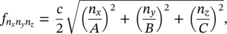
where A, B, C are the room dimensions in the x, y, and z directions, and nx = 0, 1, 2, 3,…; ny = 0, 1, 2, 3,… and nz = 0, 1, 2, 3, … Note nx, ny, and nz are the number of half waves in the x, y, and z directions. Note also for the room case, the eight propagating waves add together to give us a standing wave. The wave vectors for the eight waves are shown in Figure 3.33.
There are three types of standing waves resulting in three modes of sound wave vibration: axial, tangential, and oblique modes. Axial modes are a result of sound propagation in only one room direction. Tangential modes are caused by sound propagation in two directions in the room and none in the third direction. Oblique modes involve sound propagation in all three directions.
We have assumed there is no absorption of sound by the walls. The standing waves in the room can be excited by noise or pure tones. If they are excited by pure tones produced by a loudspeaker or a machine that creates sound waves exactly at the same frequency as the eigenfrequencies (natural frequencies) fE of the room, the standing waves are very pronounced. Figures 3.34 and 3.35 show the distribution of particle velocity and sound pressure for the nx = 1, ny = 1, and nz = 1 mode in a room with hard reflecting walls. See Refs. [23, 24] for further discussion of standing‐wave behavior in rectangular rooms.
EXAMPLE 3.16
Calculate all the possible natural frequencies for normal modes of vibration under 100 Hz within a rectangular room 3.1 × 4.7 × 6.2 m3.
SOLUTION
Table 3.3 gives all the possible natural frequencies for modes under 100 Hz using Eq. (3.94) and c = 343 m/s.
One can see in Table 3.3 that the frequency spacing becomes smaller with increasing frequency and that there may be degenerate modes present (i.e. when two or more modes have the same characteristic frequency but different values of nx, ny, and nz). Modes which are close to each other in frequency can easily “beat,” while degenerate modes can greatly increase the response of the room at particular frequencies where degeneracy occurs. This can give rise to the “boomy” sensation (at low frequencies) which is often found in regular‐shaped rooms of similar wall dimensions [4].
Table 3.3 Frequencies (less than 100 Hz) for a 3.1 × 4.7 × 6.2 m3 rectangular room, for c = 343 m/s.
| nx | ny | nz | fE |
|---|---|---|---|
| 0 | 0 | 1 | 27.7 |
| 0 | 1 | 0 | 36.5 |
| 0 | 1 | 1 | 45.8 |
| 0 | 0 | 2 | } 55.3 |
| 1 | 0 | 0 | |
| 1 | 0 | 1 | 61.9 |
| 0 | 1 | 2 | } 66.3 |
| 1 | 1 | 0 | |
| 1 | 1 | 1 | 71.8 |
| 0 | 2 | 0 | 73.0 |
| 1 | 0 | 2 | 78.2 |
| 0 | 2 | 1 | 78.0 |
| 0 | 0 | 3 | 83.0 |
| 1 | 1 | 2 | 86.3 |
| 0 | 1 | 3 | 90.7 |
| 0 | 2 | 2 | } 91.6 |
| 1 | 2 | 0 | |
| 1 | 2 | 1 | 95.7 |
| 1 | 0 | 3 | 99.7 |
The position of the sound source within the room is also an important parameter, since for many source positions certain types of modes may not be excited. For example, if the source is located in one of the corners of the room, then it is possible to excite every normal mode, while if the source is located at the center of a rectangular room then only the even modes (one eighth of the total number of possible modes) can be excited. Similarly if we keep the position of the source constant and measure the sound pressure throughout the room we see differences in level depending on where we are standing in the room relative to the normal modes. In this way the room superimposes its own acoustical response characteristics upon those of the source. Hence we cannot measure the true frequency response of a sound source (e.g. loudspeaker) in a reverberant room because of the effect of the modal response of the room. This interference can be removed by making all the wall surfaces highly sound‐absorbent. Then all the modes are sufficiently damped so we are able to measure the true output of the source [4]. Such rooms are called anechoic (see Figure 3.22).
Leave a Reply