3.7.1 Sound Power of Idealized Sound Sources
The sound power W of a sound source is given by integrating the intensity over any imaginary closed surface S surrounding the source (see Figure 3.7):
(3.41)
The normal component of the intensity In must be measured in a direction perpendicular to the elemental area dS. If a spherical surface, whose center coincides with the source, is chosen, then the sound power of an omnidirectional (monopole) source is
(3.42)![]()
(3.43)
and from Eq. (3.35) the sound power of a monopole is [4, 13]
(3.44)![]()
It is apparent from Eq. (3.44) that the sound power of an idealized (monopole) source is independent of the distance r from the origin, at which the power is calculated. This is the result required by conservation of energy and also to be expected for all sound sources.
Equation (3.43) shows that for an omnidirectional source (in the absence of reflections) the sound power can be determined from measurements of the mean square sound pressure made with a single microphone. Of course, for real sources, in environments where reflections occur, measurements should really be made very close to the source, where reflections are presumably less important.
The sound power of a dipole source is obtained by integrating the intensity given by Eq. (3.40) over a sphere around the source. The result for the sound power is
(3.45)![]()
The dipole is obviously a much less efficient radiator than a monopole, particularly at low frequency.
EXAMPLE 3.7
Two monopoles of equal sound power W = 0.1 watt at 150 Hz, but pulsating with a phase difference of 180° are spaced λ/12 apart. Determine the sound power of this dipole at 150 Hz.
SOLUTION
We know that l = λ/12, λ = 343/150 = 2.29 m, and Wm = 0.1 watt. If we compare the sound power of a dipole Wd with that of a monopole Wm (Eqs. (3.44) and (3.45)) we find that

Therefore, the sound power radiated by the dipole is 9 mW.
In practical situations with real directional sound sources and where background noise and reflections are important, use of Eq. (3.43) becomes difficult and less accurate, and then the sound power is more conveniently determined from Eq. (3.41) with a sound intensity measurement system. See Ref. [22] in this book and chapter 106 in the Handbook of Acoustics [1].
We note that since p/ur = ρc (where ρ = mean air density kg/m3 and c = speed of sound 343 m/s) for a plane wave or sufficiently far from any source, that
(3.46)
where Eq. (3.46) is true for random noise as well as for a single‐frequency sound, known as a pure tone.
Note that for such cases we only need to measure the mean‐square sound pressure with a simple sound level meter (or at least a simple measurement system) to obtain the sound intensity from Eq. (3.46) and then from that the sound power W watts from Eq. (3.41) is
(3.47)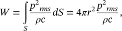
for an omnidirectional source (monopole) with no reflections and no background noise. This result is true for noise signals and pure tones that are produced by omnidirectional sources and in the so‐called far acoustic field.
For the special case of a pure‐tone (single‐frequency) source of sound pressure amplitude, ![]() , we note that
, we note that ![]() and
and ![]() from Eq. (3.47).
from Eq. (3.47).
For measurements on a hemisphere, W = 2πr2 p2rms /ρc and for a pure‐tone source ![]() , and
, and ![]() , from Eq. (3.47).
, from Eq. (3.47).
Note that in the general case, the source is not omnidirectional, or more importantly, we must often measure quite close to the source so that we are in the near acoustic field, not the far acoustic field. However, if appreciable reflections or background noise (i.e. other sound sources) are present, then we must measure the intensity Ir in Eq. (3.41). Figure 3.8 shows two different enclosing surfaces that can be used to determine the sound power of a source. The sound intensity In must always be measured perpendicular (or normal) to the enclosing surfaces used. Measurements are normally made with a two‐microphone probe (see Ref. [22]). The most common microphone arrangement is the face‐to‐face model (see Figure 3.9).
The microphone arrangement shown also indicates the microphone separation distance, Δr, needed for the intensity calculations [22]. In the face‐to‐face arrangement a solid cylindrical spacer is often put between the two microphones to improve the performance.
EXAMPLE 3.8
By making measurements around a source (an engine exhaust pipe) it is found that it is largely omnidirectional at low frequency (in the range of 50–200 Hz). If the measured sound pressure level on a spherical surface 10 m from the source is 60 dB at 100 Hz, which is equivalent to a mean‐square sound pressure p2rms of (20 × 10−3)2 (Pa)2, what is the sound power in watts at 100 Hz frequency?
SOLUTION
Assuming that ρ = 1.21 kg/m3 and c = 343 m/s, so ρc = 415 ≈ 400 rayls:

then from Eq. (3.47):


EXAMPLE 3.9
If the sound intensity level, measured using a sound intensity probe at the same frequency, as in Example 3.8, but at 1 m from the exhaust exit, is 80 dB (which is equivalent to 0.0001 W/m2), what is the sound power of the exhaust source at this frequency?
SOLUTION
From Eq. (3.41) ![]() (for an omnidirectional source). Then W = 1.26 × 10⁻³ watts (the same result as Example 3.8).
(for an omnidirectional source). Then W = 1.26 × 10⁻³ watts (the same result as Example 3.8).
Sound intensity measurements do and should give the same result as sound pressure measurements made in a free field.
Far away from omnidirectional sound sources, provided there is no background noise and reflections can be ignored:
(3.48)![]()
(3.49)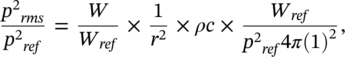
and by taking 10 log throughout this equation
(3.50)![]()
where Lp is the sound pressure level, LW is the source sound power level, and r is the distance, in metres, from the source center. (Note we have assumed here that ρc = 415 ≅400 rayls.) If ρc ≅ 400 rayls (kg/m2s), then since I = p2rms/ρc
So,
(3.51)
Leave a Reply