Selection of material
Factorability and reliability were also considered.
Based on this Aluminum T6 7075 were selected.
Module m = 3 mm (assume)
Gear ratio G = 16 (assume)
Pressure angle φ = 20°
Helical angle is from 20° to 45° (take α = 30°)
Number of pinion and gear teeth ZP=7 teeth (assume)
Required
Dimensions of pinion and gear
Check the wear, bending, dynamic and other strength of gear
| S. No. | Parameters or Dimensions | General formula | Pinion dimensions [mm] | Gear dimensions [mm] |
| 1 | Module (m) | 3 | 3 | |
| 2 | Transverse pitch (Pt) | Pt = π*m | 9.42 | 9.42 |
| 3 | Number of teeth (Z) | 112 | 112 | |
| 4 | Pitch circle diameter Do | Do = m*Z | 21 | |
| 5 | Addendum | 0.8*m | 2.4 | 2.4 |
| 6 | Deddendum | 1*m | 3 | 3 |
| 7 | Root circle diameter Dr | Do-2* deddendum | 15 | |
| 8 | Crown circle diameter Dk | Do + 2* addendum | 27 | |
| 9 | Depth of the tooth (h) | Addendum + dedendum | 5.4 | 5.4 |
| 10 | Depth of working tooth (hw) | 1.6*m | 4.5 | 4.8 |
| 11 | Tooth thickness (t) | 1.5708*m | 4.7124 | 4.7124 |
| 12 | Fillet radius at root | 0.4*m | 1.2 | 1.2 |
| 13 | Minimum clearance (c) | deddendum-addendum | 0.6 | 0.6 |
| 14 | Face width b | b = 1.15*Pt/tan α | 18.7633 | 17.7633 |
Gear Parameter Analysis
- The normal and axial pitch of the pinion and gear can be determined from the geometric analysis of the figure below.
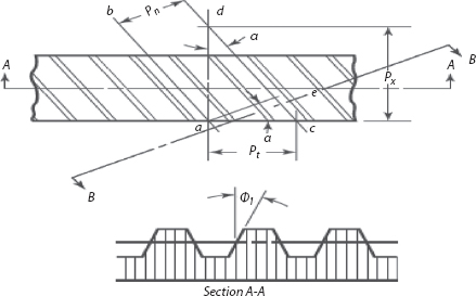
pn = ptcosα = 9.42 cos30° = 8.158mm
px= pt/tan α = 9.42 mm/tan30° = 16.316mm
The transverse pressure angle φt = tan-1 (tan φn/cosα) = tan-1 (tan 20°/cos30°) = 22.8°
(same for all gears and pinions)
Force analysis
Beam Strength of Gear Teeth – Lewis Equation
The maximum value of the bending stress (or the permissible working stress), at the section BC is given by
Iσw = M.Y Y=t/2
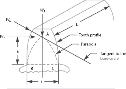
Where, M = Maximum bending moment at the critical section BC =WT×h,
I = Moment of inertia about the center line of the tooth = b.t3/12,
By substituting these values into the above equation we get;
Lewis equation is applied only to the weaker of the two wheels. When both the pinion and the gear are made of the same material, then pinion is the weaker.
Permissible working (bending) Stress for Gear Teeth in the Lewis Equation
According to the Barth formula, the permissible working stress,
Where σo= Allowable static stress, and
Cv= Velocity factor
 for the peripheral velocities 5m/s to 10 m/s.
σp =180.33
σw = 180.33× 0.545=98.36 MPa
600 = σw × 19 × π*3*0.175
σw= 19 Mpa The factor of safety F.s = 98.36 Mpa / 19Mpa = 5.3, therefore the calculated face width b is satisfactory.
Leave a Reply