The Longitudinal Location of CG
W -Total car weight,
Rf -Ground reaction at front
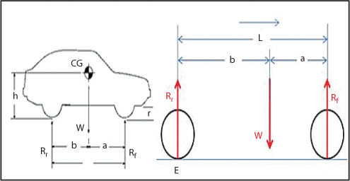
Rr-Ground reaction at rear
RR-Ground reaction at right wheels
RL -Ground reaction at left wheels
L -wheel base
T -car track
a –position of CG behind the front axle
b -position of CG in front of the rear axle
x –position of CG from the right wheels
y –position of CG away from the left wheels
The distance between the center of the front and rear wheels (L) can be written as:
(1)![]()
(2)![]()
(3)
Measure the car front axle weight Wf = Rf, and the car rear axle weight Wr = Rr.
Use equation (4) to find the car weight W.
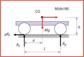
Take moment around point E.
(5)
Where his given as,
Equlibrium equations,
But the allowable velocity of vehicle before rising in turning is 30km/hr.
Using this we have to find velocity of vehicle after rising.
h= the location of the CG from the ground before rising.
h1 = the location of the CG from the ground after rising.
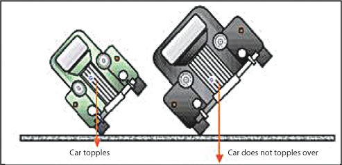
The car can rise up to 20 cm
The allowable velocity of vehicle before rising in turning is 30km/hr.
But the allowable velocity of vehicle after rising in turning in order not to roll the vehicle is 22.5km/hr.
Leave a Reply