The use of the ball in the hydraulic system is to control the flow of oil out of the cylinder. The ball is pushed by the spring. In order to not go through the spring the ball should have the same or larger diameter than the spring. There is no head to design the ball. This diameter of the ball is taking from standard table. There forms the diameter of the ball is taken to be 12mm.
Material selection
Based on the nature of the load on the ball that is compressive load we select material which is hardest and strongest steel, which is martensitic steel.
Design of Pedal
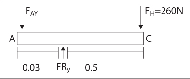
The pedal is used to transmit force from the human operator to the small piston called plunger. Also used to pressurize the fluid inside actuator and push the required force. In order to design it based on shearing and bending let us put it horizontal and find the minimum shear and bending diagram.
Assumption
In order to get good functioning and get free space we assume in our design the operation is made by inserting its holder, and you can take it from holder while finishing your work.
Material selection
Due to the nature of load applied by the person on the handle we choose gray cast iron (4.5% C, ASTM A-48).
Let us use factor of safety for the compensation
Where, Fa load of design.
Assumption
x = 30 mm
human effort = 260N
Where θ = angle
leke of handle
From assumption FH = 260
Design analysis
Using section method,
From the formula,
This force is thrash out the distance 0.03m because shearing stress between concentrated load and reaction is constant.
Maximum bending moment is |M| = |130|
Let us assume that b = 2h
Let F.S = 1.25 because it is not big work
Leave a Reply