Introduction
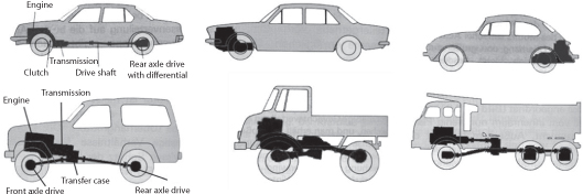
The transmission helps to transmit power from the engine to the wheels. It consists of gears, shafts, and other electrical connections. It is composed of systems shown in Figure 2.1:
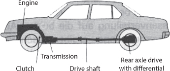
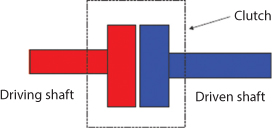
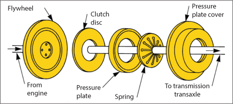
2.2 Clutch
This part is used to engage and disengage the engine from drive. It allows the driver to control the power flow between the engine and transmission or transaxle operating by the friction principle.
Need for Clutch
- Allows gradual engagement of two rotating plates
- Provides positive linkage capable of transmitting maximum engine torque
- Rapidly separates engine from drive train and reengages engine to drive train
- Provides force between pressure plate and flywheel to load clutch disk
Transmission of torque depends on:
- Size
- Engagement time
- Free pedal play
- Rate of Heat loss
- Easy in operation
- Balancing of mass
- Lightness
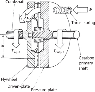
Power flow from one unit to another can be controlled with a drive disc and a driven disc.
Thus, the clutch can transmit twice as much torque
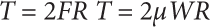
For multi-disk clutch T = (n–1)µWR
Where,
W – Spring force (N)
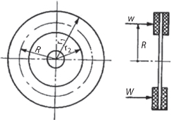
r2 – External radius (m)
r1 – Internal radius of (m)
n – Number of contacting pairs
µ – Coefficient of friction
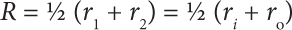
Mean radius is given as:
Tangential force is given by F = µW
Friction torque is given as T = F × R = ½ µW (r1 + r2)
Since there are n pairs so:

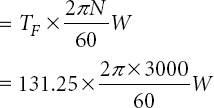
If N is speed of the clutch then the power transmitted is given as:

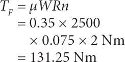
Example 4.5
A single-plate clutch of 0.15 m effective diameter is lined with material of coefficient of friction 0.35. If the total spring force is 2.5 kN, Calculate:
- the torque transmitted
- the power transmitted at 3000 rev/min.
Solution
Total spring force, W = 2.5 kN = 2500 N
Effective radius, R = 0.075 m
Pairs of contact surfaces, n = 2
Coefficient of friction µ = 0.35
Rotational speed, N = 3000 rev/min
- Torque transmitted,
- Power transmitted
Leave a Reply