It is difficult to obtain the idealized conditions of random incidence, diffuse sound fields, and absence of flanking transmission in laboratory situations. In real buildings (field conditions), such conditions are impossible to obtain in practice. However, as discussed before, it is sometimes necessary to determine the TL of a partition in the field where flanking transmission is present. Also, it may be necessary to determine the NR between two rooms in a building to determine whether a minimum NR requirement has been met to satisfy a building regulation code. Thus, for on‐site measurements, it may be necessary to consider the use of one of the methods described as follows.
a) Field Transmission Loss (Apparent Transmission Loss)
If it is required to determine the field transmission loss TLF of a partition (apparent transmission loss ATL) when flanking paths (mechanical and air leaks) are present, then an equation similar to Eq. (12.72) may be used. TLF is related to the NR = Lp1 − Lp2 as follows:
(12.79)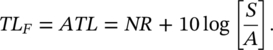
The symbols are the same as those used in Eq. (12.78). Note that ATL is known as the apparent sound reduction index (R‘) in Europe and in ISO standards. In practice, Eq. (12.79) can be used. Since flanking transmission will be present, it is likely that TLF will be less than the TL measured in the laboratory. This will particularly be true if the partition TL is high. If the laboratory TL is found to be between 35 and 50, then TLF may be expected to be 1 or 2 dB less because of flanking.
b) Normalized Noise Reduction Difference
Often, for regulation or building code purposes, it is more convenient to measure the NR between a transmission (source) room and a receiving room. However, since the NR = Lp1 − Lp2 will be dependent upon the absorption area in the receiving room (caused by furnishings, etc.), it is usual to give a normalized NR, NRN. There are two ways in which this normalization can be made. The first is to correct the NR to give the NR which would have been obtained if a reference absorption area A0 were present in the receiving room:
(12.80)![]()
where Lp1 and Lp2 are the space‐averaged sound pressure levels in the transmission and receiving rooms, A is the measured absorption area in the receiving room, and A0 is a reference absorption area, usually A0 = 10 sabins (m2) or 108 sabins (ft2). Note that NRN is known as the normalized level difference (Dn) in Europe and in ISO standards. The sound pressure levels are spatially sampled in the transmission and receiving rooms using fixed microphone positions, mechanically‐scanned microphones, or a manual scanning technique that employs a hand‐held microphone or a sound level meter. Note that when A is measured, using the reverberation time method, the quantity A + τS is actually measured, but this is of no great consequence, except perhaps at low frequency. Both ASTM [78] and ISO [79] standards define an alternative normalization procedure based on the reverberation time in the receiving room, TR. In this procedure, the normalized NR (or the standardized level difference DnT in ISO standards) becomes
Equation (12.81) results from the fact that in many furnished rooms with moderate absorption, the reverberation time is about 0.5 second, and is almost independent of room volume. Thus, using the Sabine equation: [80] A0 (m2) = 0.32 V (m3), and substituting A0 into Eq. (12.80) gives Eq. (12.81). Note that use of Eq. (12.81) results in a normalized NR value 10 × log(0.032 V [m3]) higher than the value using Eq. (12.80). This is easily seen since
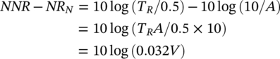
if the Sabine equation TR = 0.161 V/A is used again. Thus, whenever normalized NRs are determined, the receiving room volume should be noted and reported to facilitate conversion from one normalization procedure to another.
It is known that strong modal responses occur in room volumes less than 25 m3, which is typically the case of many rooms in dwellings. In these cases, there are often less than five room modes below 100 Hz and consequently the sound field does not approximate to a diffuse field. Therefore, the sound isolation of partitions measured in small room volumes may be under or overestimated at low frequencies. The current ASTM standard [78] states that the transmission and receiving room volumes must be not less than 60 m3 for measurements down to 100 Hz, 40 m3 for measurements down to 125 Hz, and 25 m3 for measurements down to 160 Hz. In order to improve the repeatability of low‐frequency TL measurements, the recently published ISO 16283‐1 standard [79] describes a procedure for using additional microphone positions to sample the sound pressure near the corners of rooms for frequencies below 100 Hz. Then, the average sound pressure level in the room is obtained from the sound pressure levels measured at the central zone and at the corners of the room using an empirical weighting.
EXAMPLE 12.18
A wall panel of mass/unit area of 5 kg/m2 and area 4 m2 is placed in the “window” between two reverberation rooms of a sound transmission suite. The walls of the receiving room have an area of 100 m2, and an average absorption coefficient α of 0.05 at all frequencies. (a) Calculate the space‐averaged sound pressure level in the receiving room at 1000 Hz, if the sound pressure level in the source (i.e. transmission) room is 90 dB at 1000 Hz. (b) Calculate the space‐averaged sound pressure level in the receiving room at 2000 Hz, if the sound pressure level in the source (i.e. transmission) room is 90 dB at 2000 Hz.
SOLUTION
- We use Eq. (12.78) NR = Lp1 − Lp2 = TL − 10 log (S/A), soTL = Lp1 − Lp2 + 10 log (S/A) = 90 − Lp2 + 10 log (4/0.05 × 100). Now, using Eq. (12.22c) we obtain: TL = 20 log(Mf) − 47 = 20 log(5 × 1000)−47 = 27 dB. Therefore

- By the same process as (a), we get that Lp2 = 56 dB.
Leave a Reply